Unfolding
|
Unfolding |
This command launches the unfolding of a sheet.
Creation stages / Use:
Click the Unfolding icon or select the Unfolding > Unfolding... command from the drop-down menu.
Check Predefined positioning it has been defined in the sheet metal part.
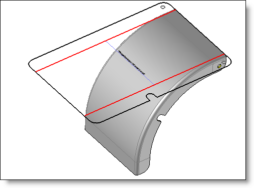
Select the reference face for the unbending.
Select if the unfolding is put on or tuned over:
|
This option allows to turn the unfolding result to 180° around the X axis of the destination frame. All bends will be reversed (upward bends become downward bends and vice versa) and also the bend angles signs |
|
The Put on mode corresponds to an usual use: The origin face is put on the destination plane of the frame. It gives the bend direction. |
|
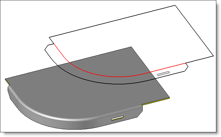
The Turned over mode allows to reverse the sheet metal regarding the selected origin face. The bend direction is inverted, otherwise we will obtain a symmetrical sheet metal of the reference sheet metal. |
Two positioning of the unfolding are available:
Position origin to select the origin point and the direction of the unfolding.
or Orient along longest length: if this option is enabled, an automatic rotation will be applied to the unfolding so that the longest length of its (minimum) bounding box is oriented along the X axis of the destination frame.
Enter the rotation angle if needed..
Select the unfolding destination frame. In this case, the center of the reference face is positioned on the XY plane of the selected frame and on its origin or check the In place unfolding option to position it on the selected face.
Select the unfolding style to use.
Validate the creation of the unfolding with the  button.
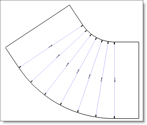
You can also force the positioning of the unfolding by checking the Position at origin box then by indicating a point in one direction, the selected point will be positioned at the origin of the selected frame and the selected direction will be merged with the X axis of the selected frame. This stage is essential when the reference face is cylindrical.
|
|
|
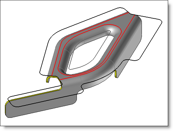
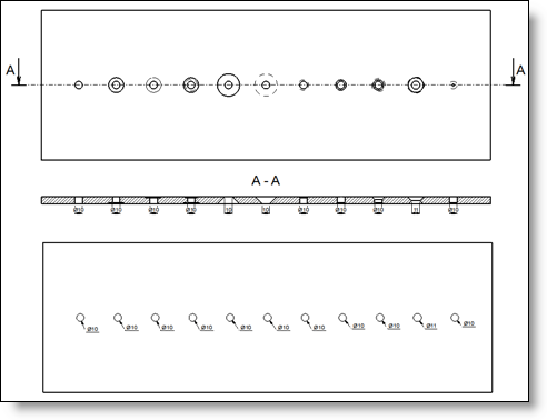
The imprinted segments can be displayed on the unfolding. They can be on plane faces, on bend, on unfolded faces. They can be in contact with borders or cut-outs or cut a part "in two parts". It is recommended to imprint them on the both sides. If not, regarding the chosen plane face, the imprinted segments will be displayed or not. |
Available Options:
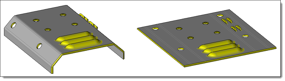
Unfolding with thickness:
|
If you're a user of the TopSolid'SheetMetal's machining module, you need to be able to work on a 3D shape so that you can manage the local deformations, the drillings/tappings, but also the chamfered parts.
|
Bends:
|
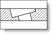
When the geometry is not Complete line, enter the extremities length of the bend line.
If there is a notch, enter the its length and width.
|
|||||||||||||||||||||||||||||||||||||||
Bend Note:
|
See the Bend Note command for details. |
Bounding box:
|
|
||||||||||||
Attributes:
|
|
Formings:
|
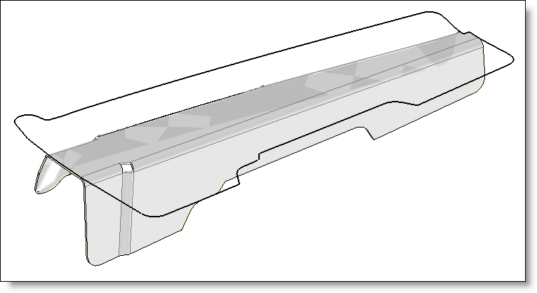
This section allows to treat areas which are not strictly unbendable. Check the "Formings treatment" option.
|
Advanced options:
|
If the hole contains some cylindrical faces, TopSolid will take as hole diameter on the unfolding, the diameter of the smallest cylindrical face (and also if the hole contains conical faces with smallest diameters). If the hole contains only conical faces,TopSolid will keep as diameter, the smallest diameter of cones. TopSolid only considers through all drillings crossing the sheet metal on the side where the origin face is selected for the unfolding.
TopSolid only considers edges "strictly" circular, which excluded tilted drillings regarding the thickness direction.
It manages geometries done by TopSolid drilling operations, but also all other kind of origin (file import, boolean operations, ...)
In general, it happens when the part has very small segments. Very often, the use of a smaller calculation tolerance allows to solve this problem. The error indicates the smallest detected segment. This option is activated by default for new unfolding documents created without template. It can be set in the unfolding style. |
Modifications / Additional information:
|
|
|
The unfolding command allows to treat multi-bodies parts. These multi-bodies are created with the Bodies mode of the Removing command. Its Keep bodies option allows to separate a multi-bodies shape in several distinct shapes. It is the selected origin face which select the shape to treat. The origin face can be predefined in the part document by using the Unfolding positioning command. Generally, sheet metal to consider must be defined in the detailed and design representations of the part document. The inclusion in the unfolding document allows to select the representation and the shape to consider. However, from the PDM point of view, the fact to have a part document with several shapes in not relevant. The best way is to use the Tools > Derivations > Partial parts... command to isolate each shapes of the detailed representation in distinct documents. These part documents are automatically included in an assembly document. |


 button
.
button
.