Unfolding Style


Links/Videos:


This command allows you to define the unfolding styles (bend representation, different colors, ...)


Creation stages / Use:


Click the icon or select Tools > Unfolding Style... from the drop-down menu.


  1. Enter a name.

  2. Check or uncheck to define this new style as default style.

  3. From the drop down list, select the style used to define the new style. If you select this option, you do not have to select again all the options, only those from an existing style.

  4. Select the different options (explanations below).

  5. Validate.


It is recommended to create a customized unfolding template document. As a result, every time a new unfolding document is created, this style will be used.


Available Options:


  • Representation:

This option selects the type of representation of the bend lines:

Center

The center line of the bend is represented on the unfolding.

Boundaries

These extremities of the bend are represented on the unfolding.

Both

These extremities and the center line of the bend are represented on the unfolding.

None

The bend lines are not represented on the unfolding.


  • Geometry:

This option selects the type of geometry of the bend lines:

Complete line

A complete line represents the bend lines.

Extremities of lines

The bends are represented by extremities of lines ( the length is defined below).

Line without extremities

The bend line stops before the sheet metal boundary ( the length is defined below).


  • Extremities length:

When the geometry is not Complete line, enter the extremities length of the bend line.


See the Bend Note command for details.


For each kind of element of the unfolding, you change its color, its kind of line and its thickness. The color can be removed by clicking the button .


  • Simplification:

  • Extract corners relief: Corners relief are not displayed on the unfolding.

  • Simplify corners relief: Corners relief will be simplified to keep constant dimensions on the unfolding without regarding the used loss at bends.

  • Extract spot facings and counter sinkings: Drillings with spot facings or counter sinkings are automatically represented on the unfolding by their smallest diameter (when this option is checked).Cylindrical and conical faces have to be coaxial.

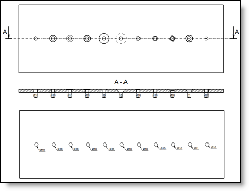
If the hole contains some cylindrical faces, TopSolid will take as hole diameter on the unfolding, the diameter of the smallest cylindrical face (and also if the hole contains conical faces with smallest diameters).

If the hole contains only conical faces,TopSolid will keep as diameter, the smallest diameter of cones.

TopSolid only considers through all drillings crossing the sheet metal on the side where the origin face is selected for the unfolding.

Example:

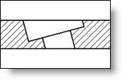
TopSolid only considers edges "strictly" circular, which excluded tilted drillings regarding the thickness direction.


It manages geometries done by TopSolid drilling operations, but also all other kind of origin (file import, boolean operations, ...)

  • Extract torn bends: This option allows to remove torn bends (bend without notches which rips the sheet metal) in the unfolding.

  • Arcs lines conversion: This option allows to transform to arcs and lines complex curves like ellipses, splines,... to allow certain machining software to read our unfolding exports.

  • Linear Tolerance: It indicates the maximum gap value authorized with simplified curves.

  • Angular tolerance: It indicates the maximum angle value authorized at the angle of tangency between two successive segments.

  • Large radius poligonization: This option, when it is checked, allows to replace by a polygon, arcs whose radius is larger than the given value, to avoid errors of punch or cut machining NC.

  • Unfolding rules:

  • Ignore local unbending processes: Some local unbending can be added to the bend with the Unbending process command of the unfolding document. These processes can be ignored.

  • Invalidity cases:

  • Presence of complex formings: By checking this option, the presence of formings or other complex deformations will make the document invalid.

  • Presence of quasi developpable faces: Remember what is a quasi developpable surface.

  • Open external profile: Allows to make invalid the unfolding if the external profile is open.

In general, it happens when the part has very small segments. Very often, the use of a smaller calculation tolerance allows to solve this problem.

The error indicates the smallest detected segment.

This option is activated by default for new unfolding documents created without template. It can be set in the unfolding style..

  • Conversion in unfolding:

  • Keep sketch colors: In sheet metal cutting industry, a lot of companies use dxf files where the color of profiles and segments are used to indicate the settings of cut to use. This option allows you to keep the color of sketches converted to unfolding (instead of colors associated with the types of contours: internal, external, ...). These colors are also transferred to the edges and the lateral faces of the unfolding with thickness (deactivate the visualization of the lateral faces to see the color applied to them, command Visualization> Display Lateral Faces ...).


Modifications / Additional information:


You can modify the different options or delete a style from the entity tree, in the Styles folder.