Swept flange
|
|
Swept flange |
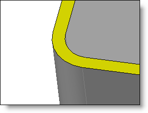
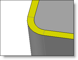
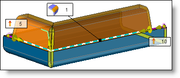
This command creates a flange along a path of edges on a piece of sheet metal
Creation stages / Use:
Click the  icon or select Sheet Metal > Swept Flange... from the drop-down menu.
Select the edges of the flange (path), the edges selected must be boundary edges connected to each other.
Enter if needed Radii to ignore. It is possible to enter a radius to define edges to ignore along the path of the swept flange. This value is optional.
Select the mode for defining the generator of the swept flange:
|
Profile |
|
||||||||||||||||||
|
Length + angle |
|
Validate the creation of the swept flange with the  button.
Available Options:
Bends:
|
|
|
By checking this option, you can add bends to each used edge. These bends can be defined by different ways: The indicated radius corresponds to the inner bending radius. |
||||
|
|
|
Manual: The radius has to be entered. |
||||
|
|
|
Thickness: The radius is synchronised with the thickness of the sheet metal. |
||||
|
|
|
Unfolding rules: The radius of bend to use is search in the table defined in the unfolding rules associated to the part. According to the thickness of the sheet metal to consider, TopSolid uses the first favorite bending radius found in the list of available radii.
|
||||
|
|
|
The Delimit bends option allows to isolate faces of the bend from those of connected faces for example to be able to use the covering.
This option can be activated by editing the command or by using the Delimiting of Bend command.
|
Edge Relief:
|
|
|
By checking this option, you can enter the gap and extension values of the edge relief. |
||||
|
|
|
Shifting value: This parameter controls the gap between the two faces of the edge relief:
|
||||
|
|
|
Extension value: This parameter controls the release for the relief tool. When the faces are not perpendicular, without extension, the edge may not be fully broken. In this case, the sheet is not unbendable.
|
||||
|
|
|
The edge relief can only affect the part created by the swept flange or it can extend along the tangent edges:
|
Offset:
|
|
|
An offset value can be added at the start and end of the edge path. This function is not available when the path is closed. |
|
|
|
Example of swept edge with offset at the start and end of the path |
Notches: