Unfolding rules


Links/Videos:


This document allows you to define the behavior of unfoldings (loss at bends, bending methods, thicknesses, etc.).


Creation stages / Use:


Create a new document by clicking the icon, then select the icon in the Special tab.


  1. Unfolding rules have to be defined in several rubrics explained below:


  2. Save and check in this document.


  • When this document is checked in, it is listed in predefined rules drop-down list from the unfolding rules command of the sheet metal.

  • To force a bend tool whatever the bending radius, choose the unfolding rules command from the predefined rules of the sheet metal.


Different rubrics of the tables tab are:


  • General properties:


  • Enter the description of the unfolding rule.

  • Enter the part number of the unfolding rule.

  • Tables definition mode: the selected mode allows you to complete tables following your choices by entering thickness, radii and corresponding tools, or by entering the radius/thickness ratio.

  • Default unbending method: Check or not this option. If activated, select a method among the different proposed. In this case, if the unbending method is not defined for the chosen thickness, radius, it is the default method which will be used. Otherwise, the unbend will fail.


All sheet shaping processes deform the material. These distortions cause the material to elongate or contract.


There are two main modes for calculating losses in bends:


- Calculations by neutral fiber:

The sheet metal length is considered as constant at the neutral fiber. But the neural fiber position changes along the thickness regarding materials or bend characteristics.


Under the neutral fiber, the material is compressed, on the neutral fiber it is stretched.


The most elementary method is to provide the neutral fiber to be applied (K factor, position of the neutral fiber) directly, but there are also other methods for calculating this coefficient depending on the material, thickness and bend radius (DIN6935).


Another option is also to store these coefficients in tables based on material, thickness, bend radius and bending tool used.


Characteristic lengths in a neutral fiber calculation


- Loss calculations on draft:

The length of the unfolded sheet is assimilated to the internal or external face lengths that are extended to eliminate bends.

There are three types of calculations: internal, external or tangent dimension.

Internal dimension

Loss calculation on draft for internal dimension:

External dimension

Loss calculation on draft for external dimension:

Tangent dimension (internal or external)

Loss calculation on draft for external tangent dimension:


  • K factor: This factor corresponds to the position of the neutral fiber.


  • Correction: Additional losses can also be applied to the results produced by different calculation modes (correction), the values of which can also depend on the material, thickness, bend radius and bending tool used. Therefore, these values are generally stored in tables.


  • Hem bends unbending method: Check or not this option. Hem bends are often designed with nominal values of internal radii and bending angles whose are not defined in the unbending tables. This occurs an fail during unfolding operation or a non adapted unfolding method for this kind of bends.

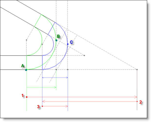
By checking this option, unbending length calculation will be precise for this kind of bends

By using this option, a precise calculation of unfolding lengths for this kind of bends is done.

This option is activated by default in the flat unfolding rules provided with the mechanical library (internal, external and tangent dimensions).


Hem bends are bends created with the Sheet metal > Hem bend command. Bends coming from an imported shape and converted to sheet metal with the Sheet metal > Sheet metal recognition command, can not be recognized as hem bends.


  • Tables:

  • In the first table (green background), enter the different sheet metal thickness or if ratio has been selected, the different radius/thickness ratio

  • If couple is selected, enter the different radii and corresponding tools to use in the middle table (yellow background)These tools have to be defined in Bending tools tab.

  • Enter the different angles, unbend methods, K factors and the correction for each angle. (table with orange background).

  • Check "Interpolate angles" so the unbend method will find a solution for non entering angles.


  • After entering the 2 first angles (0° and 15° for example), use the "Complete" contextual command to add automatically angles up to 180° by keeping the same gap.

  • Preferred bending tools: For a given thickness, several unfolding processes with the same radius may have been defined. In this case, the unfolding fails because for the corresponding bends, TopSolid can't find an unfolding rule (if no method has been defined by default).

The « Preferred » column, in the Bending processes table (yellow background),allows to define a tool to select as preferred.

If a process is defined as preferred and several tools are available, TopSolid will use the preferred.

You are allowed to check several processes in the same column (it can be different radii values for the same thickness), but if several processes with the same radius are defined as preferred, TopSolid will display a message.

If several processes for the same radius are defined as preferred, TopSolid will use the first found during the unfolding.

For a given bend, it is possible to force a different bend tool than the preferred.

  • To be able to enter  and calculate bends lost regarding the new tables given by Trumpf, LVD, ... a real radius of bend for each angle can be entered in the unfolding rules. This radius is optional.

It can only be entered for internal or external tangent dimension methods. For other methods, it has no sense, and the column is emptied.

If this value is entered, the unfolding will be calculated as if the part has been designed with this radius.

For bending angles < 90°, regarding the below scheme, it will be calculated following the [AC]points instead of the tangent dimension following the [AB] points which correspond to the design radius.

For bending angles > 90°, the calculation do not change and correspond to an external or internal tangent dimension.

Bending notes will display these real radius information (radius, unrolled dimension, k factor or equivalent). So the displayed radius will have a different value regarding the bending angle. It is recommended to also display the bending tool in the bending notes.

Also the bend boundaries will be displayed the the unrolled dimension corresponding to this real radius.

When designing the part, the used radius is not important. It is recommended to use the radius associated to the bending tool. The automatic radius option allows to automatically obtain this value.


Different rubrics of Bending tools tab are:


  • Table: Define the different tools you want to use. These must have a different description but may have the same radius. For example, the 2mm radius can use 2 different Ves of 12 mm, on for Air coining, the other of Coining. The Ve and flange widths are not essential.


Th: thickness of the sheet metal.

R: it is the "theoretical" radius of bends which is automatically associated with the tool. When the sheet metal is unfolded, TopSolid will associate the tool with the same radius for each bend. This radius is not the radius of the bending punch or the real obtained radius which also depends of the bending angle. Generally, as the global ve is imposed to unfold, this property is not widely used.

With Amada tables, this radius is given for each ve.

With the latest Trumpf tables, the real radius is given for each angle.

V: width of the ve.

B: boundary width. It gives the minimum distance between the center of the bend and the boundary of the part to be able to be used with the ve.

This value is not used by TopSolid, the field can be empty.


  • Priority of bending types: By checking this option, it is possible to define priorities of different bending types by selecting the wanted bending type and by moving it with the blue arrows. Priorities are only used if a same radius has 2 different tools and if the bending process for this radius is defined to No tool in the (Tables tab).


Different rubrics for process tab are:


This tab allows you to have access to treatment properties for developable or «almost developable» surfaces.

Developable surface definitions:

A lot of definition are possible, but intuitively, each surface which is possible to create with a lofted surface between two curves or a curve and a point can be considered as developpable for the unfolding operation.

Examples of developpable surfaces:

- Cylinders

- Cones

- Extruded surfaces

- Inclined cylinders

- Inclined cones

- Inclined pipes

- Helix

These surfaces are characterized by the presence of linear section curves in one or two of their main directions.

Strictly speaking, a surface is unfoldable if, along one of each section curve, all normals to the surface are parallels. In the opposite case, the surface is said "quasi developpable".TopSolid allows to unfold this kind of surfaces, but they are modified by adding an additional deformation, so they are not strictly "rollable".

With transition part, we are sometimes forced to use this kind of surfaces, if the additional deformation is low. In this case, we add some intermediate folding lines to allow the manufacturing by crunch faces. If this deformation is too important, the shape obtained after manufacture will not be strictly the same the initial surface used to create the unfolding.

    • Limit bending radius: This value indicates the maximum radius from which cylindrical surfaces will no more be bended but rolled or crunched.

    • Rolling: This value indicates that developpable surfaces must be unrolled by using the associated approximation tolerance. Warning, for small size surfaces (and particularly for cones), the proposed default value (0.01mm) is a bit too high and it can be punctually lowered to 0.001mm.

    • Breaking: This section indicates that developpable surfaces have to be crunched, that is to say decomposed to several bended parts. It is possible to indicate a default number of bending lines or ask the system to automatically calculate the number of bending lines to use regarding the spacing value between the lines. This spacing is the waranted minimum value, it means that two lines will have at least this distance between themselves. The spacing is calculated on the center of the surface.

    • Spacing: It is possible to enter the number of bending lines or enter a gap between bends, then TopSolid automatically calculates the number of bending lines (always >= 3, so that two successive bends are near the gap on the middle of the bends, but never under this gap).

    • Intermediate bending lines: These lines decompose the surfaces between two generatrix into two triangles. The use of these intermediate bending lines is needed when unfolding quasi developpable surfaces.

    • Alternate intermediate bending lines.

    • Internal bending radius: indicates the bending radius for each crunched line.

    • Check internal bending radius equal to thickness if needed.