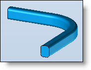
Lofted shape
|
|
Lofted shape |
This command allows you to create a shape by selecting a profile, segment or face.
Creation Stages / Use:
Click on the icon or choose the command Surface > Lofted... from the drop down menu.
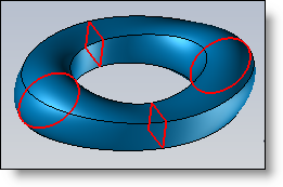
Choose the type of loft: closed or open (periodically or not).
Select loft profiles.
Choose the synchronization mode.
Choose if you want the lofted shape to be surfacic or solid.
|
|
To define the sections of a loft, it is possible to select a sketch, a segment of a sketch, or a planar face (only for the extremities sections of the loft) |
Available Options:
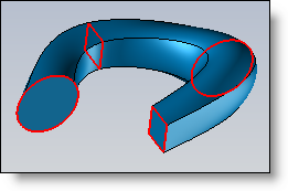
Closed:
|
|
This option creates a periodic loft, turning back on itself. TopSolid also links the first and the last section.
|
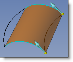
Surfacic:
|
|
If you check this check box, then the lofted shape will be surfacic and open at its extremities |
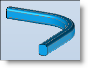
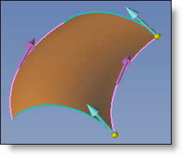
Guides:
|
|
Guide profiles constrain the lofted shape to change along the profile between sections.
|
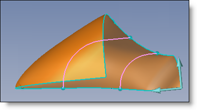
Options on section labels:
|
|
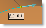
On each section, there is an arrow and a label.
The arrow's hook point corresponds to the origin of the section, and the arrow indicates the profile's direction. All sections must be in the same direction.
You can either edit the value in the label (Coefficient varying from 0 to 1), or dynamically move the point indicated by the label by dragging it with the mouse. Another way is to double click the symbol of the label to switch to point, double click again to edit the label and select a point.
|
Tangency and curvature constraints (popup menu on the section):
|
|
To use this option, right-click the desired section and select "Add Constraint".
This option allows you to apply a constraint to the lofted shape at this section. There are two types of constraints:
A coefficient defines the magnitude of the tangency. The higher the coefficient, the more the tangency is pronounced.
|
Guides synchronization:
|
|
The synchronization represents the way TopSolid make the section correspond with each other.
Example: The parametric extension for a line is [0;1] (length) The parametric extension for a circle is [0;360] (angle)
|
Correspondence points:
|
|
This option defines points of correspondence between sections in order to structure the change of the lofted shape. You can:
When you enable this option, a box appears, where you add all of the points (in order) for a set of correspondences. Once the set has been defined, validate it with
|
Correspondence:
|
|
Different types of correspondence are:
|
Division of faces:
|
|
|
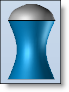
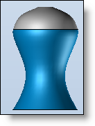
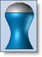
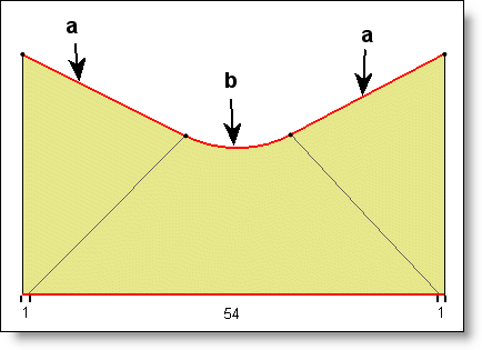
Derivation magnitude:
|
|
This option allows to smooth or not the derivation magnitude between profiles.
|
Simplify Surfaces :
|
|
This option simplifies the geometry of some surfaces. By default, surfaces from this command are b-spline surfaces. According to the reference profiles, some surfaces could be simplified into planar, cylindrical or conical surfaces. |


 . You can then select the next list of points. Once all correspondence point sets have been defined, click
  in the box to finish defining correspondences.