Unfolding rules
|
Unfolding rules |
This command allows to define or select sheet metal unfolding rules. In this case, the preferred radii for the current thickness are automatically proposed during the sheet metal creation and also all the associated unfolding parameters.
Creation stages / Use:
Click the  icon or select
Sheet Metal > Unfolding
Rules... from the drop-down menu.
icon or select
Sheet Metal > Unfolding
Rules... from the drop-down menu.
Select an unbending method.
Indicate the position of the neutral fiber (K factor) and any additional losses if applicable (correction).
Validate the unfolding rules with the  button.
Available Options:
The Predefined Rules option allows you to use the rules defined in the Unfolding Rules document (bend tables).
These Predefined rules can be of two types: Document (selection of a single rule) or Parameter (selection of Unfolding rules parameter or Switch unfolding rules parameter). Parameter allows to drive the rule with a family document or according to a material.
By checking Imposed Bend Tool, the bend tool to apply is defined no matter the internal radius defined in the design (in the "standard" case, the bend tool is selected based on the associated bend radius).
|
|
|
Imposing the bending tool at that time means that you do not have to do it when creating the flattening (you can therefore only make this choice when creating the flattening), which is interesting if you wish, for example, to automatically generate the unfolds via the multiple flattening command.
|
Modifications / Additional information:
All sheet shaping processes deform the material. These distortions cause the material to elongate or contract.
There are two main modes for calculating losses in bends:
|
The sheet metal length is considered as constant at the neutral fiber. But the neural fiber position changes along the thickness regarding materials or bend characteristics.
Under the neutral fiber, the material is compressed, on the neutral fiber it is stretched.
The most elementary method is to provide the neutral fiber to be applied (K factor, position of the neutral fiber) directly, but there are also other methods for calculating this coefficient depending on the material, thickness and bend radius (DIN6935).
Another option is also to store these coefficients in tables based on material, thickness, bend radius and bending tool used.
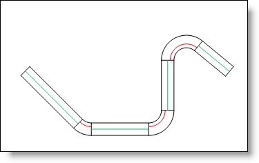
Characteristic lengths in a neutral fiber calculation |
|
The length of the unfolded sheet is assimilated to the internal or external face lengths that are extended to eliminate bends. There are three types of calculations: internal, external or tangent dimension. |
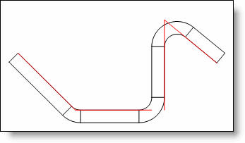
Internal dimension
|
Loss calculation on draft for internal dimension:
|
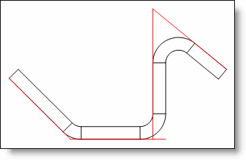
External dimension
|
Loss calculation on draft for external dimension:
|
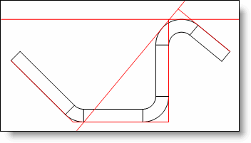
Tangent dimension (internal or external)
|
Loss calculation on draft for external tangent dimension:
|
K factor: This factor corresponds to the position of the neutral fiber.
Correction: Additional losses can also be applied to the results produced by different calculation modes (correction), the values of which can also depend on the material, thickness, bend radius and bending tool used. Therefore, these values are generally stored in tables.