|
Automatic
composite dimensions |
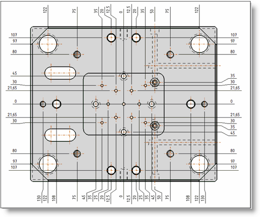
This command allows to rapidly and automatically dimension a set of
drillings with composites dimensions.
Composite dimensions are positioned following 2 directions.
Creation stages / Use:
Select the Detailing >
Automatic composite dimensions... command from the drop-down menu.
Select the view where to position composite dimensions.
Select the mode. (base line, cumulated, ordinate, continue).
Select direction axes of the composite dimensions. (axes x and y, x only, y only).
Select the composite
dimension style to use.
Validate by clicking  .
.

|
With automatic mode,
it is not possible to select axes direction. Dimensions can only
be orientated following x and/or y. If another direction is needed,
you have to use the composite
dimensions command. |

|
If the automatic composite
dimension is used on an interrupted
view, only an origin manually defined is allowed. If another
kind of origin is defined, an error message is displayed when
creating or modifying the automatic
composite dimensions operation. If there are automatic
axes in the interrupted
view, generated dimensions by the automatic
composite dimensions operation will not be hooked on
these axes. All options and settings
below are specific to automatic composite dimensions. More
general dimension settings (secondary dimension, framing,
size, extremity type, ...) are available by using a customized
dimension style or after validating the command, by editing
the dimension. |

|
With the
contextual menu : Other >
Explode, it is possible to basify dimension to independently
modify it. When this command is apply, dimension are transformed
into simple entity and
are independents. |
Available Options:

|
Allows to select the origin of coordinates.
|

|
Automatic drillings detection:
If this option is unchecked, only selected geometries are
dimensioned. If it is checked, drillings are proposed. Drillings to ignore: Allows
to select drillings of the view to ignore during the dimensioning. Extra geometries: It is
possible to add geometries (vertex, pocket edges or others,
...) to be also dimensioned. Exceptions : Among entities
to dimension (drillings and/or geometries), it is possible
to create an exception for not having a dimension following
x or y for a geometry. By unchecking the X cell, the dimension
following X for this geometry will be ignored. If the geometry
is a vertical edge, only X can be checked or unchecked, Y
is unchecked. If the geometry is a vertex, X and Y can be
checked or unchecked. |

|
Allows to configure the detection of geometries
to dimension:
Maximum tilt: By default,
the value is 0° which means that only perpendicular drillings
are detected. By modifying the angle, it is possible to also
take in account tilted drillings if they match the entered
value. Minimum arc: Lower arcs
to this entered angle will not be taken in account for this
composite dimension. Maximum diameter: Drillings
with an upper diameter to the entered diameter will not be
taken in account for this composite dimension. Minimum diameter: Drillings
with an lower diameter to the entered diameter will not be
taken in account for this composite dimension. |

|
Display the name and
size of font used
Check the Font
option to activate the button and be able to modify settings (font,
style, size,...)
Displays the number
of digits for composite dimensions.
Check the unit
format to activated the button and be able to change settings
(number of digits, show training zeros, ...)
The dimension for the
bore position can have a different number of digits by using this
option. This option is only available for base line and ordinate
modes. |

|
Allows to define the
text alignment regarding the dimension geometry.
Check the Alignment
to position the dimension text above or on the dimension line.

|
The text is positioned above
the dimension line. |

|
The text is centered on
the dimension line. |

|
The text is positioned bellow
the dimension line. |

|
The text is positioned on the
farest side the part geometry . |
In the case of a secondary dimension,
if values must be one above and the other below the dimension
line, use centered on the dimension line.
Allows to define the offset
between the dimension text and line.
Allows to define the
gap between the geometry and the projection line and also the
extension of the projection line above the dimension line. |
|
This option adapts depending on the mode selected.

|
Base
line:
Offset
between 2 lines: Allows to define the distance
between 2 dimension base lines. Extremity
symbol: Allows to define dimension extremities
regarding the origin and the measure.(Reminder: extremities
dimensions are set in the dimension style or by editing
the dimension). |

|
Cumulated:
|

|
Ordinated:
Origin
dimension: The original dimension can be shown
or hidden (value 0). Dimension
line: The dimension line can be shown or hidden. Extremity
symbol: Allows to define dimension extremities
regarding the origin and the measure.(Reminder: extremities
dimensions are set in the dimension style or by editing
the dimension). |

|
Continue:
|
|
With
fragment |
With
change terminator and export |
|
|

|
Positioning distance:
Allows to set the distance between
the dimension line and the reference geometry.
When a dimension has been moved,
the contextual menu on one of the automatic composite dimensions
gives access to the Reinitialize
position command. This command put back all dimensions
to the positioning distance value. |
Modifications / Additional information:
The dimension contextual menu allows to:
- delete composite dimensions
- edit composite dimensions
- edit the selected dimension
- edit the selected dimension
text
- to fragment the selected dimension projection line
- edit the tolerance
of the selected dimension
- copy tolerance
of the selected dimension to paste it on other composite dimensions
- define a dimension as mask
- hide a dimension
- dimension like (use the
style of another dimension)
- change the style
- rename
- ....