|
 Manual:
interruption profiles will be created manually. Manual:
interruption profiles will be created manually.
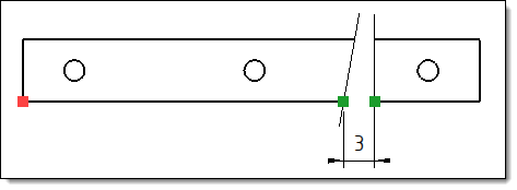
Select the direction If necessary, select a measure point
on the view. With non parallel interrupt profiles this point
allows to define between which points to compute the offset
(see image below). The next step allows you to draw
the interruption sketch. The next step allows you to give
the offset value (spacing between interruption profiles) and
to modify their attributes.

|
Example
of the use of an axis measure point (red point). The offset
of 3mm entered by the user is calculated between the green
points, resulting from the intersection with an axis passing
through the measuring point. |
 Manual
Standard: interruption profiles are selected from a
list of predefined types. Manual
Standard: interruption profiles are selected from a
list of predefined types.
Select the direction. Edit
existing interruption: when the selected view has already
been interrupted, it is possible to activate this option in
order to complete the existing interruption instead of creating
a second interruption operation. This option will remain grayed
out if the selected view contains several interruptions made
separately. Select a type of predefined interruption
profile (line, wave, zigzag or small zigzag). Enter the offset value (spacing between
profiles defining an interruption). Modify the attributes of the interruption
profiles if necessary. Position the profiles on the view
(you can place as many as you need). Validate.
 Automatic
Standard: this mode allows to automatically interrupt
a view, taking into account the topology of the part. Automatic
Standard: this mode allows to automatically interrupt
a view, taking into account the topology of the part.
Select the direction. Select a type of predefined interruption
profile (line, wave, zigzag or small zigzag). Enter the offset value (spacing between
profiles defining an interruption). Minimal length: only shapes
that are longer than the minimum length will be interrupted. Mode:
Minimum
size of interrupted area: only areas whose size is greater
than n% of the total length will be interrupted.

|
Example
of an automatic interruption in the minimum
size mode of the interrupted area mode of 15%.
Only
areas larger than 75mm (15% of 500mm) will be interrupted. |
Sum
of interruptions: TopSolid interrupts the areas as long
as n% of the total length is less than the sum of the interruptions.
The areas to be interrupted are considered in descending order
(from the largest to the smallest).

|
Example
of automatic interruption in sum
of interruptions mode of 65%.
Only
areas whose sum is less than 325mm (65% of 500mm) will
be interrupted.
Areas
of 150mm and 100mm are interrupted because: 150mm + 100mm
= 250mm < 325mm.
The
90mm area is not interrupted because: 150mm + 100mm +
90mm = 340mm > 325mm. |
Shrinkage factor: this option
allows you to shift the profiles of the geometry. Necessary
to avoid overlapping profiles when two areas to be interrupted
follow each other. TopSolid averages the interruptions found
(whether possible or not), applies the factor to this average
and shifts the profiles with the result. If a shrinkage factor
of 10% is set in the above example, the interruption profiles
will be shifted by 7.14mm (10% of (500mm / 7 interruptions)). Modify the attributes
of the interruption profiles if necessary. Validate.

|
Operations
at the ends of the shape will not be interrupted if they
are contained in an area less than 20% of the total length
of the shape.
They are still used in the calculation of the areas
to be interrupted (especially in the Sum
of Interruptions mode).

|
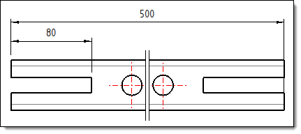
Example of an
automatic interruption in the Minimum
size of interrupted area of 15%.
Although the 80mm
operation is greater than 15% of the total length
of 500mm it is not interrupted because it remains
less than 20% of the total length. |
|
|

 icon or select
the View > Interrupted
view... command from the drop-down menu.