To be able to use the extruded bars, it is essential that the libraries required for the project be referenced beforehand. The referencing is done via the Add reference contextual command from the references icon in the project tree.
|
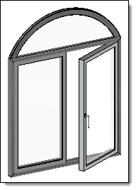
Extruded bar |
This command positions the extruded bars in the assembly.
Creation stages / Use:
Select Modeling > Extruded Bar... command from the drop-down menu.
|
To be able to use the extruded bars, it is essential that the libraries required for the project be referenced beforehand. The referencing is done via the Add reference contextual command from the references icon in the project tree. |
Select a type of extruded bar in the drop down list.
Select the code of the extruded bar in the drop down list.
|
This command allows you to position an extruded bar on each selected edge, segment, profile or face.
|
|
This command positions the extruded bar by selecting its 2 end points. |
|
This command positions the extruded bar on a frame and indicates its length. |
|
This command allows to position the extruded bar by constraint positioning.
|
Enter the orientation of the extruded bar. The orientation is a rotation around the longitudinal axis.
Check or uncheck the Reverse extruded bar. This option reverses the direction of the extruded bar.
Select the offset type by clicking one point in the extruded bar preview of the dialog. The selected point becomes blue. The longitudinal axis of the extruded bar will be on this point. It can also be changed by double-clicking one of the yellow points (in the graphic area)
If required, enter the value of the horizontal offset.
Select the type of vertical offset from the drop down list.
If required, enter the value of the vertical offset.
|
|
|
|
|
|
Available Options:
Substituable in upper levels:
This option allows to authorize the substitution (replacing) of the extruded bar when the assembly document is included into another assembly. When it is not checked, the extruded bar will be greyed in the substitution dialog box. See the sub-component substitution command for more details. |
Modifications / Additional information:
To modify the type of extruded bar, its offset, its orientation, use the Edit contextual command.
The extruded bar family can contain drivers to be able to modify them during extruded bar inclusion.
An extruded bar can be an assembly to allow to manage a different material for each part of the assembly as for example a extruded bar with a seal.
During the in place edition of an extruded bar, it is possible to associatively hang on the assembly.
The Replace contextual command allows to interchange several extruded bars at the same time.
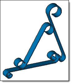
Curved extruded bar:
|
|
|
|
Extruded bar components can be included on 2D or 3D sketch with splines or arcs. Into a sketch, tangent curves will create a single curved extruded bar. |
|