Automatic Nesting
|
Automatic Nesting |
This command allows to automatically place several Parts documents on a support with any form by entering the quantity of each part.
Creation stages / Use:
Select the Nesting > Automatic nesting... command from the drop-down menu.
Activate the Parts tab. Drag the parts to nest from the project tree.
Activate the Supports tab. Drag the parts to nest from the project tree.
Select the strategy.
Select the options.
Validate by clicking  .
.
|
This command is protected by a license. |
|
|
Calculation mode:
|
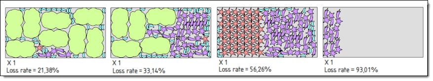
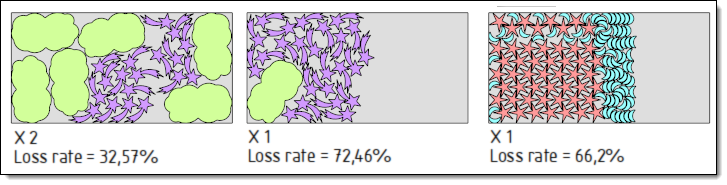
Two modes of nesting calculation can be applied:
|
The nesting window is composed of seven tabs:
Parts:
|
This tab allows to select the parts to nest by dragging them from the project tree and by filling the placing informations (quantity, gaps, rotation, ...)
To be able to be added to this list, a part document must be able to provide at least one nesting section (2d). A part can be placed if it follows these rules:
In each case, the section plane will be the positioning plane of the part in the nesting. If the machining frame is defined, its X axis is used to define the 0° orientation of the part rotation angles.
Parts and supports priorities are independently considered.
This option allows to flip the part on the support in order to gain in loss rate. In order that a flip part is properly placed inside the support, TopSolid must knows its thickness. For a sheet metal part this value is retrieved automatically, otherwise it must be entered in the Nesting characteristics. Into the nesting document, part quantity is global (flipped part or not).
|
Supports:
|
This tab allows to define the list of supports to use to nest parts and the nesting characteristics (quantities, border gaps).
|
Strategy:
|
This tab allows you to define the nesting strategy, several strategies can be complementary:
|
Checking:
|
It is possible to allow supports and parts without material. In this case, there will be no error.
|
Options:
|
This tab allows to manage colors, default values for security gaps of the parts and the supports, for the gap between supports, the text style to use and the template to use. These defaults values and options allow to fill the new documents dragged in this nesting. If a part has a security gap defined with the nesting characteristics command, it will be used.
|
Created documents:
|
|
Nestings:
|
|
Modifications / Additional information:
 Complete and
  Recompute options are useful only to complete or recompute
an existing nesting. They appear by using this command with an existing
nesting document.
Recompute options are useful only to complete or recompute
an existing nesting. They appear by using this command with an existing
nesting document.
Local parts nesting:
|
For local parts nesting, drag-and-drop the assembly in the automatic nesting window, validate the question for local parts nesting and select local part to nest.
|
|
To use a symmetrical part a Mirror part must be created and it must be added to the parts to nest. When creating the mirror document, the Nesting characteristics analysis operation is derived too with the rules below:
|


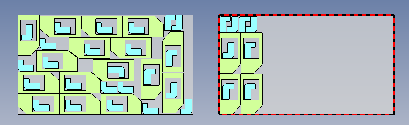
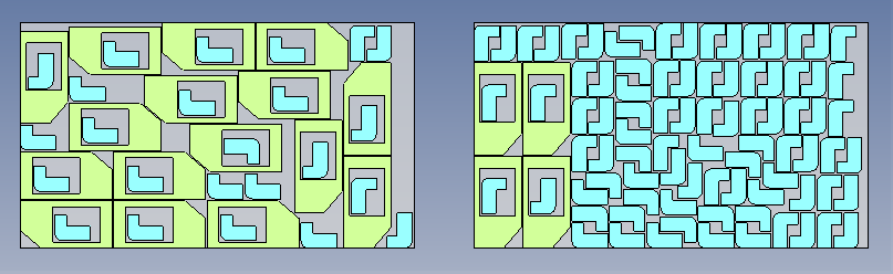
 Nesting by enclosing box:
 Maximum filling
 On the left: