|
|
Document Part or assembly |
|
|
Analysis Preparation Document |
|
Resolution Launch |
|
|
|
Document Result 1 |
|
|
Document result 2 |
|
|
Document result ... |

|
|
TopSolid'FEA |
Presentation:
TopSolid'FEA is a module that allows you to perform a static or modal analysis in the elastic domain of the material. These analyses are based on the finished items method.
An analysis of deformations, proper frequencies, etc. can therefore be obtained.
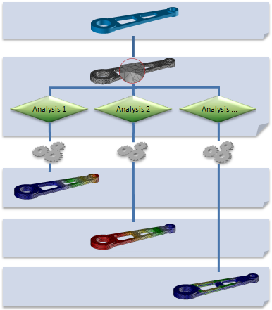
Following is an organization of documents that gravitate around this module:
|
|
||||||||||||
|
|
Options available in TopSolid'FEA also depend on your module. |
|
|
|
TFEA Express |
FEA Standard 7 |
FEA Pro 7 |
|
Structure type |
Solid |
|
|
|
|
Beam and Shells |
|
|
|
|
|
Assembly |
|
|
|
|
|
Maximum Number of Nodes |
50,000 nodes |
No Trim |
No Trim |
|
|
Analysis type |
Linear Static |
|
|
|
|
Linear Buckling |
|
|
|
|
|
Modal |
|
|
|
|
|
Thermal |
|
|
|
|
|
Thermomechanical |
|
|
|
|
|
Fatigue |
|
|
|
|
|
Quick Solver |
|
|
|
|
|
Calculation Report |
|
|
|
|
|
Availability |
Free with TopSolid'Pro |
Profitable |
Profitable |
|
 Part Document:
It is the document where the part has been built.
The material allocated to the part must have the following information:
Density
Young Module
Poisson's Ratio
 Calculation Preparation Document:
This document contains the meshing of the studied part as well as the definition of different analyses that should be studied.
You can perform different types of analysis: Linear Static, Linear Buckling, Modal, Thermal, Thermomechanical and Fatigue.
Several analysis cases can be defined in the same preparation document.
Each case of analysis created in this document generates a new result document associated with this analysis.
 Resulting Document:
This document is automatically generated when the resolution of one of the defined analyses is launched in a calculation preparation document.
Each analysis of the "calculation preparation" document generates a separate result file.
This document allows you to view the results of:
Static Analysis
Main constraints, from Von Mises and from Tresca
Displacements
Modal Analysis
Proper frequencies
Distortions
Buckling Analysis
Stages of Analysis:
The part analysis is done with some specific commands.
Simplified, here are the stages of an analysis:
Include the part or the assembly to analyze.
Use the Analysis | Include part or assembly or drag the part or assembly document from the project tree to into the analysis document.
Structure creation
The sketch and shape commands are available to prepare parts or assemblies before meshing. Indeed, documents created by the R&D department should not be modified, but it is sometimes necessary to modify them in the analysis document to remove details or having only the neutral fiber. Then use commands
Mesh creation
Use these commands
Analysis creation
Use the Analysis | New Analysis command.
Loadings definition:
Use command panel
Definition of limit conditions
Use command panel
Calculation resolution
Use the Analysis | Resolution command.
Result view
A new "result" document associated with this analysis is created.
In the case of a static analysis, you can view the results with the following commands:
In the case of a modal analysis, you can obtain the proper frequencies of the part.
To do this, use the Results | Proper Frequencies command.
Report creation
You can generate a report for each analysis.
To do this, use the Results | Report Generation command.