Automatic Parting Surfaces


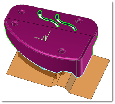
This command automatically creates a batch of parting surfaces that are external to the part. The command will create Extension, Planar, Lofted without guides, and Lofted with guides, types of surfaces available in the Parting Surface command.

It is possible to manually create, during the command process, a set of parting surfaces on which the calculated surfaces will be based.


Creation stages / Use:


Click the icon or select the Split > Automatic Parting Surfaces... command from the drop-down menu.  


  1. Select the shape to treat.

  2. Choose the Parting line to take into account.

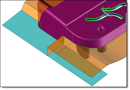
  3. Compute surfaces, and keep or not those proposed.

  4. Validate .


  • Only the external parting lines will be considered by the command.
  • The parting line edges must be completely defined for the command to be able to correctly determines the closed parting lines to be considered.


Available options:


  • Shape with shrink: Select the shape around which to create the surfaces. If only one shape to split is present, it is selected by default.
  • Mold frame: The opening frame is chosen by default. The planar type surfaces created by the command will be created firstly on the XY plane of the chosen reference frame.
  • Limit: This option allows you to determine the length of the created surfaces. Two modes are available:
    • Length: You enter the length of your surfaces.

    • Stock plane: The created surfaces will be trimmed by the stock planes.

  • To choose the parting line to consider, two modes are available:
    • Full:  The closed and external parting lines to the shape to split are listed. The surfaces will be created from these lines, if they are checked for calculation.
      It is possible to reverse the direction of the edge path and/or choose another Start Edge. This has an influence on the surfaces that will be created. Each surface can depend on the one created before it.
    • Partial: Selecting a start edge and an end edge allows you to create a partial parting line, and to create surfaces only on this selection.
      It is possible to reverse the direction of the path created between the two selected edges.


Parting edges selection : Partial mode

  • Automatic update:
    • If this mode is activated, the calculation of the preview of the created surfaces is automatically restarted after each modification on parting surface, manual addition of new parting surfaces and/or vector profiles. It is recommended for processing simple to medium complex parts.
    • To process complex parts, it is possible to disable this mode. In this case a button is available: Calculate surfaces. This button starts the calculation of the preview of the automatic surfaces. It is greyed out if no additional calculation is required.
  • Surfaces Priority:
    • Planar: This mode is the default creation mode. Priority is given to planar surfaces (in the XY plane of the selected reference frame).
    • Extension : In some cases, the priority given to planar surfaces during the calculation does not allow the most relevant result to be obtained. Indeed, flat surfaces are created in Part extension mode if no nearby surface can give direction, which can lead to large surfaces "covering" the others. This option allows you to give priority to extension surfaces during the calculation.


It may be interesting to first start the calculation in Planar mode, Validate the desired planar surfaces and then restart the calculation in Extension mode.


Surface priority Planar 

Surface priority Extension.


  • Surfaces: Each created surface is added to this list of surfaces, and its preview is visible on the screen.  
    • It is possible to choose to create or not each of these surfaces:
        • By checking or not this one in the list.
        • By pressing the Delete key after selecting undesired surfaces in the graphic area.


    • It is possible to choose to Edit the surfaces automatically created:
        • Contextually from the list.
        • Or Contextually after select it in the graphic area.

The command starts the classic editing of parting line surfaces. It is possible to modify the options for creating the surface, including changing its type: Extension to Lofted for example.

The editing context is different, however. The other automatic parting surfaces are shown either in preview color (indicating that they can be used to  modify the surface) or in wireframe (indicating that they cannot be used).


Automatic parting surface editing context.


    • It is possible to choose to Validate the surfaces automatically created:
        • Contextually from the list.
        • Or Contextually after select it in the graphic area.

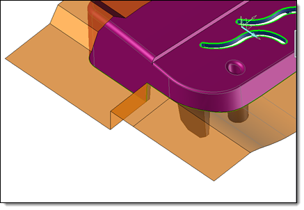
The command validates the selected surface(s). Validation consists in considering the surface as an already existing surface. It will therefore be moved to the section Parting surfaces. It will no longer be recalculated, and the new automatic surfaces will be based on it. As a result, the result before and after the validation of a surface is not necessarily identical.


  • This panel contains all existing parting surfaces ( shot off included) when calculating the surfaces.
  • It is possible, by contextual command from the list of surfaces or by graphic selection to:
    • Edit surface: The command starts editing the surface. The editing context is the same as that of automatic parting surface editing. The only difference is that existing surfaces created after the edited surface are not shown.
    • Delete: This command deletes the selected surfaces.
    • Parting surface: It is possible to create a new parting surface, which will be added to the existing parting surfaces. The command is also accessible from the graphic area.


This section lists the vector profiles that can be used to create the surfaces (the vectors connected to a free parting edge).

  • It is possible to consider them or not, for creating surfaces by checking or unchecking each of the profiles.

  • It is possible to create a new Vector Profile by launching the contextual Vector Profile command in this area. The command is also accessible from the graphic area.

  • By means of the contextual command Edit Vector Profile, it will be possible to modify the profile selected in this list or in the graphic area.


  • These options include the Fitting and Smoothing options that are offered when creating the parting surface.  Some parting surfaces can only be created at certain tolerance or smoothing values.  It is therefore useful to try to modify these tolerances in the event of failure to create the surfaces.

  • Validate edited surfaces: This option allows you to automatically validate a calculated surface when leaving its edition.


Modifications / Additional information:
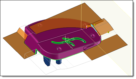