Parting Shells


Links / Videos :


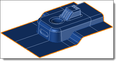
This command allows to generate the Parting Shells, according the Shape to Split, the Parting Edges and the Parting surfaces you previously defined.


Creation stages / Use:


Click the icon or select the Split > Parting Shells... command from the drop-down menu.


  1. You visualize the different shells created related to your parting design.


It is possible to "double-click" or use the F2 key to rename the selected Shell in the list.


  1. Once checked, validate to create the Parting Shells.

Available options:


If you want to animate only one Shell, select it before the cursor handling.


  • Shells: This option lists the different shells that will be created by the command. A shell will produce one block or one insert.


For each selected shell in the previous list or from the graphics area, it is possible to :

  • Tool shapes: A shell is composed of the sew of a molding area of the part and the Parting surfaces connected thereto. It is possible to modify the list of the surfaces to be sewn.

  • Tolerance: This option defines the sewing tolerance between the faces. For two surfaces to be able to be sewed together, the edges common to these two surfaces must not be farther apart than the sewing tolerance.


It is possible to set this tolerance by default in the document options: Options, Split Blocks, Parting Shell.


  • Number of iterations: Using this option, you can optimize the sewing of a set of faces.

    • If you validate the function, a first sewing is made as per the tolerance given. However, surfaces that are too far from each other will not be sewn.

    • The value of the tolerance is thus multiplied by 2 and new sewing of the remaining surfaces occurs with this new tolerance.

    • The value of the tolerance is then multiplied by 2 again and so on; as many times as the number of iterations.

For example, for a initial tolerance of 0.01mm and a number of iterations of 3, here is what will happen:

    • first sewing at the 0.01mm tolerance

    • second sewing has a tolerance of 0.02mm  (0.01mm x 2)

    • third sewing at a tolerance of 0.04mm (0.02mm x 2)


The maximum number of iterations is 10. And the minimum number is 1 (the first sewing).


  •  Merge: This option allows you to remove from the shell the smooth edges produced by the sewing.

    Creating the shell without the option.

    Creation of the shell with the Merge option.


  • Opening direction: This direction allows you to visualize the opening direction of the future block produced with the selected shell. It is important to check if this direction is the wanted one, because it will be used to create the Movement Prismatic Joint of the inserts, in the mold with the Mold joints command.

  • Opening distance: This distance makes it possible to limit the opening of the shell when one simulates its movement by the opening cursor.


  • Each change of options in this section causes a recalculation of the edited shell. It is possible to disable the shell creation preview in order to be able to make any desired changes more quickly in case of complex surfaces.


  • Check: This option allows you to launch automatically the Check command to control the geometrical validity of the parting shells produced.
    This option is not activated by default, because the calculation can be quite long.
    However, it is necessary to Check the shells geometry before launch the Parting shapes command. Indeed invalid shells will produce invalid parting shapes and invalid blocks.
  • Ignore small edges: This option can be useful in the case where the parting edges are composed of many very small edges.  It will allow a better association between the parting surfaces and the different parting shells.


Modifications / Additional information:
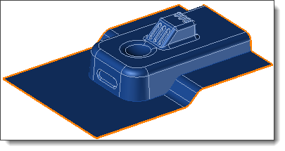