Scale:


  • Absolute: The view's scale factor does not take into account the plane's scale factor. The value applied is simply the value entered.


  • Relative to the plane: The view's scale factor is the result of the multiplication between the plane's scale factor and the value entered.


  • Relative to: The view's scale factor is the result of the multiplication between the reference view's scale factor and the value entered. This option is not available for a main view.


Title:


  • Visible Title: This cell allows you to modify the visibility attribute of the title.


  • Position: Select the position to assign to the text here. It is possible to drag the title view where you want (Free). By approaching the title near the view, it is automatically snapped to this position. To deactivate this snap, press the Alt key and move the title.


  • Text: By activating this option, you can edit the contain of the title. The feature of this option works the same way than the creation of a Rich text.


Visible lines / hidden lines / visible smooth lines / hidden smooth lines / auxiliary lines / boundary lines / piping neutral lines / explosion lines


  • Visibility: By default, the visibility mode used is that defined in the view style used. It is possible to specify another mode: visible or hidden


  • Attributes: If you select the Attributes cell, you can configure the stroke type, the thickness and the color (the Empty Color button allows you to use the original color of the projected part). When changes have been made to the part color, you have to regenerate the drafting document to retrieve the new color in the views. The Half tone cell allows you to use the half tone of the selected color.


Points:


This option allows you to display points from 3D document into the view. In the 3D document, these points must be available in the Representation folder (available from the entities tree).


  • Visibility: By default, the visibility mode used is that defined in the view style used. It is possible to specify another mode: visible or hidden


  • Attributes: If you select the Attributes cell, you can configure the point type, the thickness, the size and the color. The Half tone cell allows you to use the half tone of the selected color. These attributes are only shown when using the exact mode. With fast mode, the point is the same as the point in the 3D document.


Render Mode:


This option allows you to modify the rendering of the view.

Four modes are available: The render mode defined into the style, the wire frame render and the shading or realistic render.

Transparency : allows to use the transparency of material (like glass) or of the attribute.

  • None : we will not use the transparency.

  • Material : we will use the transparency of the material.

  • Attribute : we will use the attribute defined in the Design.


Threading:


This option allows to manage the threadings representation. No threadings, simple threadings, accurate threadings. The threading can also be represented by a 3/4 circle. If this option is unchecked, it is represented by a complete circle. The Projection mode must be set to Exact.


Axes:


  • Line: This area allows you to modify the attributes of the axes (inherited from the style or customized). You can also display them in half-tint.


  • Extension:

Extension length: allows to extend axes extremities..

Merge distance (affects only the automatic axis):If two axes situated on the same line are far from a value inferior to the value specified in this field, they will be merged in order to form only one axis.


Hatching:


This option lets you force the color and the layer of hatchings.

However, the forced color has no priority over any changes you can make using the Edit contextual command on a hatched area.


Detailing:


This option allows you to get the detailing elements (sketches, points, dimensions and annotations) defined in the source document with the Tools > Drafting > Detailings... command.

The elements are projected when the direction defined in the Detailings correspond to the normal direction of the view.


Advanced options:


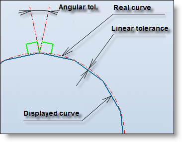
  • Projection tolerance : Enter linear and angular projection tolerances. Lower is the tolerances value, higher is the projection accuracy, but the projection calculation also increases.


  • Shapes hide profiles: When this options is active, the lines of projected profiles are hidden by the shapes when they are behind them. If the option is not active, the hidden lines of projected profiles use the same line type attribute than the hidden lines defined in the view style.


  • Position: The position of the view is dynamic. It is possible manually enter coordinates.


  • Alignment: Allows you to manage the position and the displacement according to the reference view.


- Align:

The view is aligned according to its reference view, it can be moved along the horizontal or vertical axes (except the view along a direction that can move according to the given direction). It also moves when the reference view is moved.

- Fix:

The position of the auxiliary view is fixed in the drafting document, it doesn't move when the reference view is moved.

- Follow:

The view is not aligned according to its reference view, it can be moved in all the directions. It also moves when the reference view is moved.