View Style
|
View Style |
This command allows view styles to be created / modified which will then be usable when creating a view (main view, auxiliary view, cross section, ...).
A view style is the configuration of view titles, stroke visibility and attributes (stroke type, thickness and color), cross section polygons, detail sketch, ...
Creation stages:
Select Tools > Styles > View style... command from the drop-down menu.
Give a name to this new view style.
Check Current style. This style will be proposed by default when creating a new view.
Choose the base style (the base style allows to retrieve the settings of this existing style).
|
The modification of a view style used as a basic style by another style will automatically cause the modification of the latter. |
Available Options:
Title:
|
Allows you to customize the font of the view title (font, text height, ...).
Allows to add a title to each created
view. The scale can be added to the title by clicking the |
Lines:
|
Allows to customize these lines types. They can be visible or hidden, and their attributes can be changed (type, thickness and color). - Visible lines: External edges of the part. - Hidden lines: Lines inside the geometry - Visible smooth lines: Jonction edges between tangent faces, not hidden by the geometry. - Hidden smooth lines: Jonction edges between tangent faces, hidden by the geometry. - Auxiliary lines: Axes, ... - Boundary lines : delimitation (mask, trim volume) - Piping neutral lines - Explosion lines
By default, the visibility mode is the one defined in the basic style used. It is possible to specify another mode: visible or hidden
If you select the Attributes
cell, you can configure the type of lines, the thickness and color
(the The "Half tone" cell allows the half tone of the selected color to be used. |
Render Mode:
|
This option allows you to modify the rendering of the view. Four modes are available: The render defined in the basic style, the wireframe, the shading or the realistic rendering. Transparency: allows to use the transparency of material (like glass) or of the attribute.
|
Threading:
|
This option allows to modify threading informations. Threadings can be not managed (No threading). They can also be displayed with thick lines (Simple threadings), or with fine lines (accurate threadings). The treading views from the top can be represented by an arc by checking the 3/4 circle option, otherwise it will be represent by a complete circle. |
Axes:
|
This option allows to modify axes attributes (inherited from style or customized).
This area allows you to modify the
attributes of the axes (inherited from the style or customized).
The You can also display them in half-tint.
Allows you to extend the ends of the axes. If two axes situated on the same line are far from a value inferior to the value specified in this field, they will be merged in order to form only one axis. |
Cross section:
|
This zone allows to customize cross sections (polygon, title, font, arrows, arrows and text positions, polygon color, ...)
Allows to select a type of polygon. It can be alone, with arrows or complete with arrows and text.
Allows to define the cross section
title syntax. Click the
Allows to customize the font of the cross section title (font, height, ...)
Allows to select in the drop-down list, the type of arrow for the cross section polygon.
Allows to define different settings for cross section polygon arrows.
Allows to position the text beside or behind the arrow by clicking the wanted icon.
Allows to define the overflow length of the cross section polygon regarding the crossed geometry.
Allow to position arrows regarding the cross section polygon by clicking the wanted icon.
Allows to configure the polygon line
type, its thickness and its color (the The Half tone cell allows you to use the half tone of the selected color. |
Hatching:
|
This option lets you force the color and the layer of hatchings. However, the forced color has no priority over any changes you can make using the Edit contextual command on a hatched area. |
Section:
|
This zone allows to customize sections (Polygon, title). Other settings (font, arrows, text and arrows positions, polygon color, ...) are inherited from the Cross section zone.
Allows to select a type of polygon. It can be alone, with arrows or complete with arrows and text.
Allows to define the section title
syntax. Click the |
Detail view:
|
This zone allows to customize detail views (title, font, lines).
Allows to define the detail view
title syntax. Click the
Allows to customize the font of the detail view title (font, height, ...)
Allows to configure the contour line
type, its thickness and its color (the The Half tone cell allows you to use the half tone of the selected color. |
View along a direction:
|
This zone allows to customize views along a direction (title, font, arrows, text position).
Allows to define the view along a
direction title syntax. Click the
Allows to customize the font of the view along a direction title (font, height, ...)
Allows to select in the drop-down list, the type of arrow for the view along a direction.
Allows to define different settings for view along a direction arrow.
Allows to position the text beside or behind the arrow by clicking the wanted icon. |
Interrupted view:
|
This zone allows to customize interrupted view lines attributes.
Allows to configure the interruption
line type, its thickness and its color (the The Half tone cell allows you to use the half tone of the selected color. |
Mounting stages:
|
This zone allows to customize mounting stages title. Other parameters (font, height, ,...) are inherited from the Title zone.
Allows to define the mounting stages
title syntax. Click the |
Detailing:
|
This zone allows to project detailings (sketches, points, dimensions and annotations) define in the document to project with Tools > Drafting > Detailings...
Direction define in the Detailings command is normal to the view. Linked entities are projected too. |
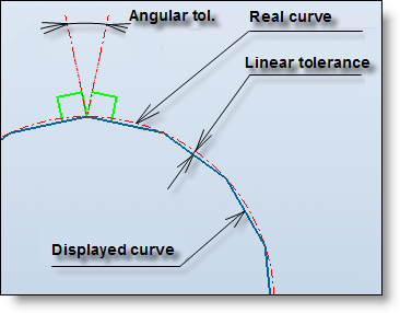
Advanced options:
|
This zone allows to modify projection tolerances.
Enter linear and angular projection tolerances.. Lower is the tolerances value, higher is the projection accuracy, but the projection calculation also increases.
|
|
|
Modifications / Additional information:


 button.
 button allows you to use
the original color of the projected part). When changes have been
made to the part color, you have to regenerate the
button allows you to use
the original color of the projected part). When changes have been
made to the part color, you have to regenerate the 


 button to add the cross section name, To obtain A-A, click the
button, add - (minus) then click again the button. This is the
result: [$Index]-[$Index]. You can also add the scale of the cross
section by clicking the
button to add the cross section name, To obtain A-A, click the
button, add - (minus) then click again the button. This is the
result: [$Index]-[$Index]. You can also add the scale of the cross
section by clicking the