Select and/or create a drilling template.
Select (or create by clicking on "+") the drilling frame.
Select the shape to drill.
Validate the command with the button 
|
Drilling |
This command allows you to perform different types of drilling operations on a part.
Creation stages / Use:
Select Shape > Drilling... from the drop-down menu (or Modeling > Shape > Drilling... in the assembly document).
Select and/or create a drilling template.
Select (or create by clicking on "+") the drilling frame.
Select the shape to drill.
Validate the command with the button
|
To be able to create tapped holes, you need to reference a library containing the standard you wish to use for the tapping. |
Available Options:
Lightweight:
|
This option allows you to not create the boolean operation, it is available for holes only. The drilling is then displayed with a circle but the operation gets all the manufacturing information for TopSolid'Cam, the Home > Create Features option must be checked as well. The drilling created this way can be repeated, it allows to design a flat part with a huge number of holes. These drillings will be displayed in the drafting document as well. |
Inoperative:
|
This option allows you to create a drilling without making the corresponding boolean operation. It is mainly useful to redefine a drilling from an imported geometry. This option concerns blind holes only. A through hole must be defined as a blind hole with a depth equal to the thickness of the part. When the Home > Create MF option is checked, the drilling operation gets all the manufacturing information for TopSolid'Cam, |
Templates and types of drilling:
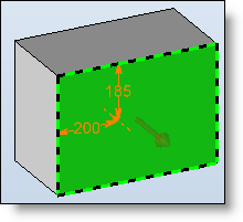
Frame:
|
With this option, you define the frame on which the drilling will be carried out.
Each drilling operation requires a frame which defines the position of the drilling and its direction. The drilling is done based on the Z- of the frame. The Z- axis must therefore be directed toward the inside of the part so that the drilling can be carried out.
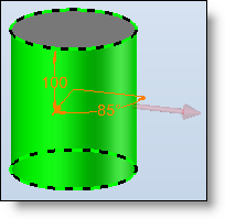
If there is no drilling frame, it can be created in a dynamic way on certain types of faces by moving the mouse over this face:
|
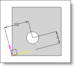
Reference frame:
|
Possibility to use a reference frame on which be based axes of the constraint frame. Regarding the constraint frame, the reference frame can be used with automatic mode only.
|
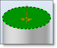
Shape to drill:
|
Select the shape on which the drillings will be done.
|
In/Out counter sinking:
|
Advanced options:
|
Origin: This option allows you to define the measurement origin of the drilling depth:
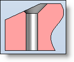
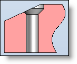
Extension process of Countersink: This option defines the countersink drilling process at the entry face. In fact, drilling starts in the origin of the frame. However, in the event of an inclined face or the presence of a shoulder next to the drilling, TopSolid needs to "extend" the drilling above the origin point to achieve a good result. These are the two possible modes:
Machining process:
Additional text: This information can be retrieved in the Additional text column of a drillings table as well as in a drilling note. This text can be created in 3 different ways:
|
Drilling processes:
|
|
Below the main options, a list of icons is displayed which allows you to modify the parameters of the different procedures of the drilling template used.
By default, the values are those of the drilling template. It is therefore not required to access this if the values of the template are those you wish to use.
See here for the detailed description of the different procedures. |