Drilling operation processes
|
Drilling operation processes |
Counter inking
|
Select this counter sinking configuration mode and fill in the corresponding values:
For the angle, two angle configuration modes can be chosen:
|
Spot facing
|
Give the diameter of the spot facing, its depth and a bottom radius if needed.
|
Screw spot facing
|
Standard: Select the screw spot facing standard you wish to use. The list proposes the screw spot facing standards available in the referenced projects or libraries
Nominal diameter: This list displays the diameters available in the selected standard. The values displayed with a white background (instead of green) are the dimensions defined as "Occasional use" in the document of this standard.
Description: Defined in the standard document
Head type: Specify the head type to use. Facing diameter will change according of this type (cylindrical or hexagon).
Diameter: Display the spot facing diameter that will be used (this value coming from the selected standard document).
Forced diameter: Possibility to impose a value other than the one coming from the standard. Possibility to use parameter with 0mm as value, in this case we use the standard value as default and if the parameter is modified with value bigger than 0mm then we will use this one.
Depth: Specify the facing depth. |
Hole
|
Diameter: Provide the diameter of the hole.
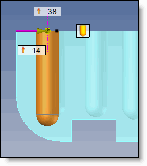
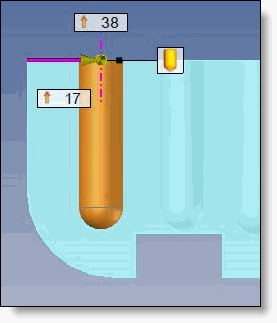
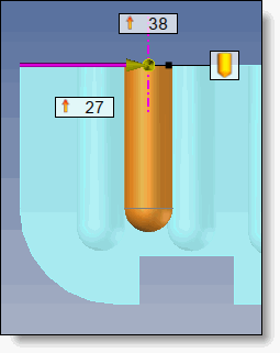
Depth: Select the depth definition mode:
For the blind hole, you can use three modes to determine the depth of the hole:
Conicity: Allows to define if the hole is conical and in this case, its angle of conicity. By default, this option is unchecked.
Bottom type: Next, define the type of end:
Total depth: This option allows to indicate that the depth is at point. |
||||||||||||||||||||||||||||||||||
Tapped hole
|
Standard: Select the threading standard you wish to use. The list proposes the threading standards available in the referenced projects or libraries
Model: This option allows to create the actual tapping shape for 3D printing.
Here's how to make a user threading standard compatible with 3D modeling:
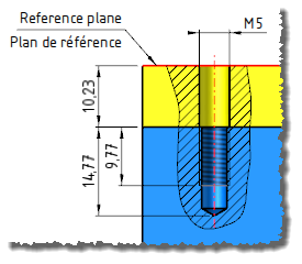
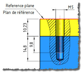
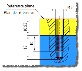
Tapping:
Hole:
Next, define the type of end:
This option allows to indicate that the depth is at point.
Advanced:
|
Clearance hole
|
Standard: Select the clearance hole standard you wish to use. The list proposes the clearance hole standards available in the referenced projects or libraries
Nominal diameter: This list displays the diameters available in the selected standard. The values displayed on a white background (instead of green) are the dimensions defined as "Occasional use" in the document of this standard.
Description: Defined in the document of the standard.
Head type: Defines the type clearance hole (Fine, Medium or Large). This determines the oversizing of the clearance hole in relation to the nominal diameter of the threading.
Diameter: Display the clearance hole diameter that will be used (this value coming from the selected standard document).
Forced diameter: Possibility to impose a value other than the one coming from the standard. Possibility to use parameter with 0mm as value, in this case we use the standard value as default and if the parameter is modified with value bigger than 0mm then we will use this one.
Depth:
|
Color :
Each drilling operation process can have its own color. Select a color by clicking the button or by using an existing one with the pipette.
Machining process: