|
Screen presentation |
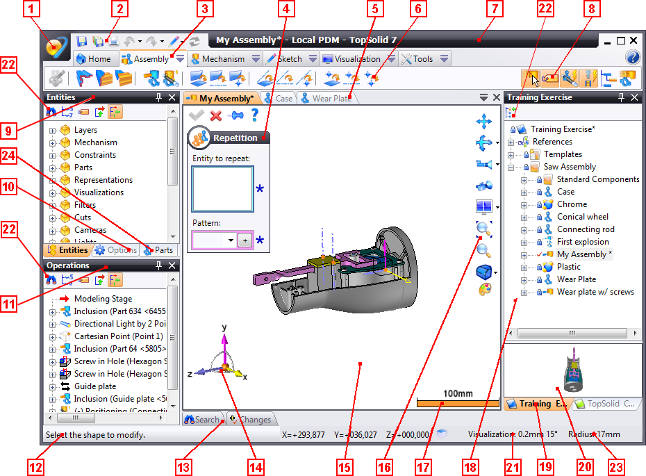
The TopSolid 7 screen consists of different zones allowing you to manage projects and documents:
1 |
TopSolid button |
13 |
Search, change and request/approval tabs |
2 |
System toolbar |
14 |
Compass |
3 |
Context and Menu Tabs |
15 |
Workspace |
4 |
Dialog Window |
16 |
Visualization and Rendering Bar |
5 |
Document Tabs |
17 |
Scale Bar |
6 |
Context Commands (Work Bar) |
18 |
Project Management Window |
7 |
Banner |
19 |
Project Tabs |
8 |
Context States |
20 |
Preview Area |
9 |
Entity Window |
21 |
Visualization tolerances |
10 |
Options Window |
22 |
Tools bar of tree |
11 |
Operations Window |
23 |
Measurement |
12 |
Dialog Area |
24 |
Parts window |
This button, also called the Application Icon, allows you to access commands for file management, editing, display, document visualization windows, PDM management and exiting the software.
This icon bar groups frequently used TopSolid commands: Open Current Document, Save All Documents, Print, Undo, Redo, Stage Change and Refresh.
Contrary to the context icon bar, it is not customizable.
This area displays the entire set of available commands. The contents of this menu depends on the type of document being edited, as well as installed add-in modules.
Right-click the text of a context tab to display context icons on the Work Bar found just below. This bar contains the most frequently used commands of the menu (you can also change the toolbar by placing the mouse cursor in this area and turning the wheel, if the mouse has one).
Left-click the  button (or right-click
the tab text) to scroll the menu. Commands are split into sub-menus that
can be accessed by clicking the arrow found at the right of the text (you
can also click the text with the right mouse button).
button (or right-click
the tab text) to scroll the menu. Commands are split into sub-menus that
can be accessed by clicking the arrow found at the right of the text (you
can also click the text with the right mouse button).
|
The
|
This area displays when the name of a command ends in "..." (such as, for example, the Sketch > Line... command). It allows you to enter different information that performs the selected command.
By default, the dialog window displays in the upper-left area of the workspace, but it can also be displayed in the form of an anchored tool window with the TopSolid > Display > Dialog command (click it to turn on the mode).
The top of the dialog window consists of an icon bar allowing you to perform basic commands:
|
OK |
Validates the dialog
and executes the current command when all necessary data is entered,
if any data is missing, this button is grayed out. You can also
run the validation by right-clicking and selecting the |
|
Cancel |
Closes the dialog
without running the current command. You can also close the document
by right-clicking and selecting the |
|
Help |
Launches the online help of the current command. You can also launch the help by pressing the F1 key on the keyboard. |
|
Preview |
Activate or not the preview of the command result. This option is only available for some commands (surfacic commands, hollow, thicken, trim, ...) which needs a lot of system resource. Performances can be increased by deactivating the preview. |
|
Thumbtack In |
Allows you to select the operation mode of the command. If the thumbtack is in, the command will automatically restart after use, which allows you to concatenate, for example, multiple fillets without relaunching the command. However, if the thumbtack is not it, the command only works once. |
|
Thumbtack Out |
|
|
Next |
When certain commands function like wizards, the Next and Back icons allow you to go forward or back in the stages. |
|
Previous |
|
|
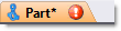
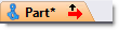
This area contains the list of open documents; each document is open in a window with a tab containing the name and icon of the type of document. It can also be followed by symbols that describe the status of the document:
Symbol |
Example |
Document Status |
* |
|
Modified Document. |
|
|
Document containing an invalid operation or item. Left-click this icon to edit the 1st invalid operation. |
|
|
Document for which the operations tree cursor was lowered in order to see the part or assembly in a previous state. Left-click this icon to move the cursor to the top of the tree. |
Document Name: Window # |
|
Document open in several windows. |
When multiple documents are open, the tab of the current document has
an orange background. Furthermore,
in the right part of the window, the 
 icons allow you to respectively display
the list of open documents in order to select the new current document
and close the current document.
icons allow you to respectively display
the list of open documents in order to select the new current document
and close the current document.
|
|
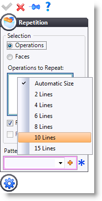
6 - Context Commands (Work Bar)
The command bar contains the most frequently used commands of the chosen context. Selecting a command generally triggers the display of command options in the Dialog Panel.
Commands are displayed in the left part of the context, whereas states (or modes) are displayed in the right part.
|
You can change the toolbar by placing the mouse cursor in this area and scrolling the wheel, if the mouse has one. |
The banner displays the name of the current document, as well as information related to the type of PDM used. In Local Mode, the Local PDM information displays, in Client/Server Mode, the name of the connection as well as the user name between brackets displays.
States (or modes) allow you to set the options of the current context, select the mode when the icon is on an orange background (orange is the default active color and can be configured in the Window feature of the Tools > Options... command).
For example, in the Sketch context, Construction mode allows you to define the construction type for the items created next.
The dialog area displays messages that guide you through each command. The right part contains the coordinates of the cursor in relation to the absolute frame, as well a progression cursor for the current command, when necessary.
13 - Search, change, request and approval tabs.
This area automatically opens when you slide your cursor over one of the tabs, in the same way that it automatically closes when your cursor remains outside the tab for a few seconds.
The Search tab allows you to search the document based on different criteria (see the Search command for details).
The Change tab allows you to quickly view documents currently open by different users connected to the same PDM server (see the Change command for details).
The Requests tab allows to visualize sent approval requests and requests to approve (workflow). (see the Requests command for details).
|
Search and Changes tabs can be displayed/hidden with the Search, Changes and Requests commands of the TopSolid7 button > View. |
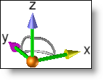
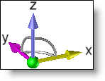
The default position (lower left) displays the orientation of the absolute frame with different sensitive areas that turn green when the cursor hovers over them, this allows you to control the orientation of each view:
Displacement of View (Panoramic): |
|
To move the view based on an axis, clicking one of the axes (represented in green in the opposite image) with the left mouse button, then move the cursor while holding down the left mouse button. |
|
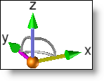
Spherical Rotation: |
|
To rotate the view spherically, click the end of an axis (represented in green in the opposite image) with the left mouse button and move the cursor while holding down the left mouse button.
For a perpendicular orientation to the selected axis, double-click the axis or the end of an axis. |
|
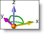
Rotation Around an Axis: |
|
To rotate around an axis, click a circle arc joining two axes (represented in green in the opposite image) with the left mouse button and move the cursor while holding down the left mouse button.
For a 90° rotation, double-click a circle arc joining two axes.
|
|
Displacement of Compass: |
|
You can move the compass by clicking the origin of the compass (represented in green in the opposite image) and moving the mouse to an item while holding down the left mouse button, then releasing the button to anchor the compass to the desired item.
The compass is positioned on a peak, a planar face or in the middle of a cylindrical, conical or spherical face and the original sphere will be replaced by a cube. When the compass is anchored on an item, the orientation of the absolute frame is materialized by a trihedral positioned in the lower left corner of the screen.
You can move the compass back to its initial position by selecting the original cube with the left mouse button, holding down the button and moving it to the void. |
|
|
|
Negative Axes: |
|
You can display the X-, Y- and Z- axes by positioning the cursor next to the assumed location of these axes, they will then appear in green and you will have the same options as for positive axes. |
|
|
|
|
|
The workspace allows you to view the document being modified. The management commands of this area (Zoom, Orientation, Multiple Windows, Rendering, etc.) are found in the Visualization menu, the most frequently used commands are grouped in an icon bar called Visualization and Rendering Bar found to the right of this area.
The mouse buttons also allow you to quickly access certain commands:
Zoom: Turn the wheel of the mouse to zoom in or out of the view.
Global zoom: Double-click on the middle button (wheel) allows you to resize all elements in the graphic area (global zoom).
Rotation: Click and hold down the middle button to turn the view contents.
Furthermore, you can indicate a rotation axis by positioning the cursor on an item (edge, segment, etc.), and pressing the Alt key on your keyboard.
Translation (Panoramic): Click and hold down the right mouse button to move the view contents.
Furthermore, you can indicate a translation axis by positioning the cursor on an item (edge, segment, etc.), and pressing the Alt key on your keyboard.
|
When the workspace is divided into multiple views, the active view is identified by a black edge, the view also contains the compass and the visualization and rendering bar. |
16 - Visualization and Rendering Bar
The visualization and rendering bar groups the most frequently used commands of the Visualization menu, these commands allow you to quickly act on the document being modified.
Icon |
Command |
|
Displacement of View (Panoramic). |
|
View rotation and access to Rotate View and Lock View commands. |
|
Face view and access to other views (above, right, etc.). |
|
Perspective View. |
|
Split workspace into 4 views and access other split commands (1 view, 2 views, etc.). |
|
Best Zoom |
|
Window Zoom |
|
Shadowed rendering with edges and access to rendering commands (see the different rendering mode commands for more details). The icon changes according to the selected render. |
|
Attributes by default. The icon changes according to the selected color.
|
|
Default line style. The icon changes according to the selected line. |
|
Default marker style (available on Drawing documents). The icon changes according to the selected marker. |
|
The contents of this bar can be modified with the Tools > Customize command. |
The scale bar allows you to have an idea of the size of the item being modeled, its value is recalculated depending on the zoom performed on the view.
|
The scale bar can be displayed or hidden by checking or unchecking the Show Scale Bar option in the Display feature of the Tools > Options command. |
18 - Project Management Window
When multiple projects are open, these tabs allow you to change the current project.
As with document tabs, you can quickly close a document by clicking the tab with the middle mouse button (wheel).
The preview area displays a preview of the selected document as long as this document was created by a TopSolid7 application.
The preview of a document is calculated from shapes contained in the document with the Shadowed Rendering with Edges, Perspective Camera and Global Zoom settings. However, some types of documents, such as threading standards or unfolding rules, do not have a preview.
Visualization tolerances can be modified by double-click on the text.
22 - Tools bar of tree
Under the tree banner, a tools bar allows to display more or less information. The options are activated by clicking the icon (orange background) and are disabled by clicking a second time.
Some icons are not available for some trees. You will the detailled description of each icon in the pages explaining the role of each trees.
|
Some modes are only available for some trees.
For example, the projects tree as no Synchronizations mode |
23 - Measurement
When you select one or more elements, a measurement is displayed on the bottom right of the screen without any command being selected.
The result depends on the type of element selected:
Selection |
Result |
Line |
Line length |
Arc or fillet |
Radius |
Circle or cylindrical face |
Diameter |
Two parallel lines or faces |
Distance between both lines/faces |
Two non-parallel lines or faces |
Angle between both lines/faces |
24 - Parts tree

 icon on the right of the


 .
.