This command defines the type of render mode to apply to the view.
Shade render mode allows you to visualize the scene with the item faces filled in, thus providing a realistic type of visualization (using what is called the "Gouraud" method).
|
Name
|
Description
|
Example
|
|

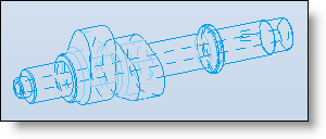
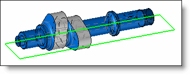
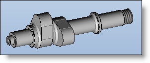
Shadow rendering with edges
|
Fill in faces.
The edges are displayed.
If sketches are visible, they cross the geometry.
|
|
|

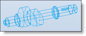
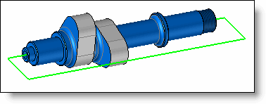
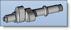
Shadow rendering with dotted hidden edges
|
Fill in faces.
The edges are displayed.
Hidden edges are visualized with dashes.
If sketches are visible, they cross the geometry.
|
|
|

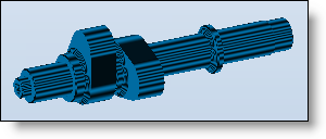
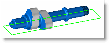
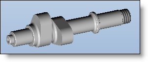
Shadow rendering
|
Only the filling of the faces is displayed.
The edges are not displayed.
If sketches are visible, they cross the geometry.
|
|
|

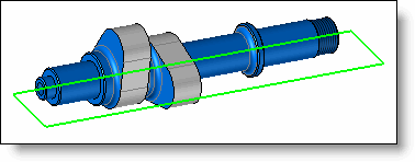
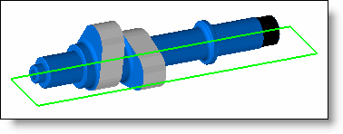
Shadow rendering with hidden wireframe
|
Only the filling of the faces is displayed.
The edges are not displayed.
If sketches are visible, they are interrupted by the geometry.
|
|
|

Constant shadow rendering
|
Calculate a unique illumination value for each facet.
The edges are not displayed.
If sketches are visible, they cross the geometry.
|
|
|
Name
|
Description
|
Example
|
|

Realistic rendering with edges
|
The materials and the coatings associated with the items are taken into account.
The edges are displayed.
|
|
|

Realistic rendering
|
The materials and the coatings associated with the items are taken into account.
|
|
|

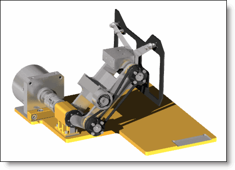
Realistic rendering with effects
|
The materials and the coatings associated with the items are taken into account as well as the shadows made by the lights.
|

|
|

Realistic rendering with effects and edges
|
The materials and the coatings associated with the items are taken into account as well as the shadows made by the lights.
The edges are displayed.
|
|
|

Progressive Ray Tracing
|
The Progressive Ray Tracing mode allows to calculate an image on the whole document’s graphics area without blocking the use of the software commands.
The rendering parameter settings are available via an icon on the top right of the graphics area.
These settings are retained when calculating an image using the Visualization > Realistic Rendering … command.
|
|