The operations window allows you to display the operations tree. This tree consists of the list of operations that allowed you to complete your document. Operations are filed in chronological order, the last operation displays at the top of the tree. Each operation is automatically named. You can rename an operation by selecting Other > Rename from the popup menu or by clicking an operation that is already selected.
When selecting an operation, an echo of the selected operation displays in the workspace.
As with the entity tree, depending on the operation status, the text representing each operation can be in different colors:
|
Color |
Operation Status |
|
Black |
Normal State. |
|
Bold |
The operation has been generated by an other operation and can't be directly edited. |
|
Gray |
The operation was not executed. |
|
Green |
The operation is being edited. |
|
Blue |
The operation is in manual refresh mode and needs to be refreshed. |
|
Orange |
The operation is out of date, it was modified, but not executed again. |
|
Red |
The operation is invalid. |
Also, if a sketch is under constrained, (some of its entities are magenta), it will be displayed with (-) as prefix
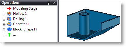
You can view the different construction stages of the document by moving the insertion cursor to the tree. When this cursor moves down, all operations above are turned off (displayed in green), if you perform a new operation, it will be inserted just below the cursor. You can move the cursor up by moving it manually, right-clicking the cursor and selecting End Insertion from the displayed popup menu or clicking the  icon found on the document tab.
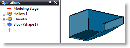
Example of using the insertion cursor:
|
|
|
|
Stage #1: Part with insertion cursor up. |
Stage #2: Lowering of the insertion cursor under the hollowing out operation. |
|
|
|
|
|
|
|
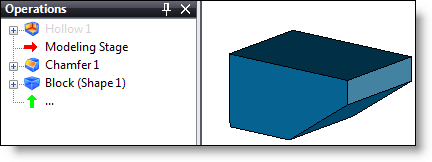
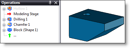
Stage #3: Drilling Creation. |
Stage #4: Moving up the insertion cursor, the hollowing out operation takes into account the previous inserted drilling. |
You can also move an operation. To do this you must select the operation by left-clicking and holding down the left mouse button, then releasing the button in the desired position.
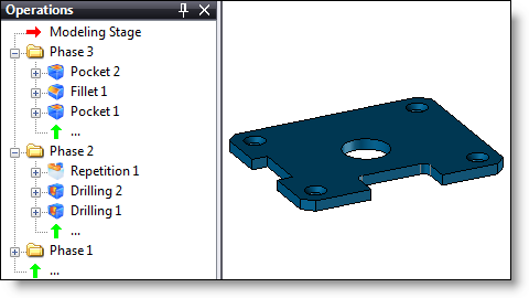
Operations can be categorized into folders, folders can be created by right-clicking the insertion cursor and selecting the Folder command. To move an operation to a folder, you must select the operation to move with the left mouse button, hold down the button, move the operation under the folder name, then release the button. As with operations, a folder can be moved or renamed.
|
|
|
Example of operations filed in different folders: |
|
|
The operations window can be displayed/hidden with the TopSolid7 button > View > Operations command. |
Under the tree banner, a tools bar allows to display more or less information or columns:
|
Icon |
Command |
|
|
Collapse all: Allows to collapse all opened sub-folders. |
|
|
Show search: A field appears to fill the beginning of a word to find it in the tree. The tree is automatically unrolled and the first matched word found is highlighted. The |
|
|
Show folders counts: Display the information counts found in the tree. For example, in the entities tree, Sketches (5) means that there are 5 sketches in this folder. |
|
|
Show definitions: If this mode is disabled, a fillet in the operations tree does not display any information. By enabling this option, an information node appears under the fillet and displays its parameters. |
|
|
Show references : Allows to display a subnode named References under the elements which depend on other elements. These latter elements appear in a list when you expand the subnode. |
|
|
Show back references: Allows to display a subnode named Back References under the elements that other elements depend on (in the same document). These latter elements appear in a list when you expand the subnode. |
|
|
Show parent and children operations: Display the parent and children operations. For example, if this mode is activated in the entities tree of an assembly, in the Parts folder, you are able to unroll ( |
|
|
Show entities: This mode, only available for the operations tree, allows to display the operations entities. By unrolling the operation, an entities sub-folder will be displayed ( |
|
|
Show synchronizations: This mode, only available for the operations tree, allows to display synchronizations (for example, parts modified according to an assembly geometry). |
|
|
Track entities/operations: When selecting an entity or an operation in the graphic area, it is also highlighted in the tree. By default, this mode is disabled in the projects tree. |
|
|
Sort entities in alphabetical order: This mode, only available for the entities tree, allows to sort entities in alphabetical order to find them easier. |
|
|
Show entities that are not available. This mode allows to show entities even if they are not available, like for example a created plane when the inserting cursor is under this plane or a parameter created in a stage located after the current stage (parameter created in the Analysis stage when the document is in the Design stage).. |
|
|
Options: Allows you to add the Execution duration column for each operation. |
|
|
Execution duration: Allows to know the execution time of each operation. It allows to identify the most time consuming operations and may be try to optimize the design. |


 icon allows to empty the field.


 ) a sub-assembly and display its positioning and inclusion. If the mode is disabled, you are not able to unroll this sub-assembly.


