These area allows to define sections count and the construction rule of section planes.
Parallel planes: construction of parallel planes sections or radial sections.
Enter points count (equivalent to sections count).
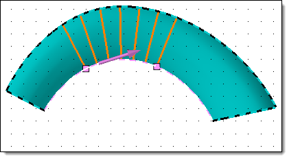
Specify if the distribution is done along a direction (parallel planes sections) or around an axis (radial sections).
Select the direction or axis.
|
|
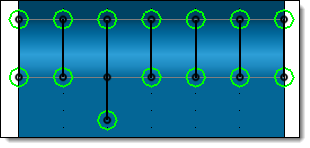
Distribution along a direction |
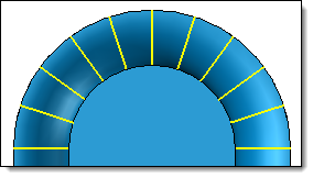
Distribution around an axis |

|
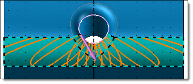
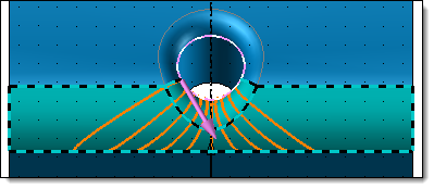
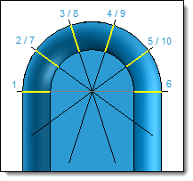
The guide profile is not trimmed with the useful part of selected faces. In the distribution around an axis, sections count is calculated at 360°. In this case we could have a planes superposition and sections superpositions.
|
|
Distribution of 10 points around an axis Sections 7, 8, 9 and 10 are superposed with 2, 3, 4 and 5
|
|
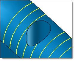
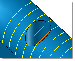
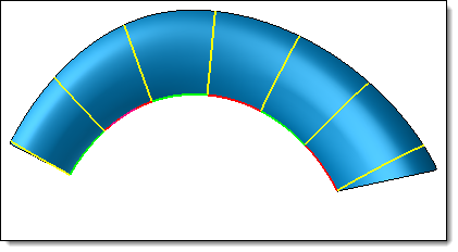
To limit sections distribution on the selected face, use the Profile extremities option. |

Guide profiles with created points:
Selected guide profiles and make sure directions are the same on all profiles.
Enter points count (equivalent to sections count).
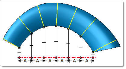
Specify the distribution mode (they are the same that in the Seedling on profile command). It can be by length profile (all points will be separated by an identical distance according to the curvilinear length), along a direction (all points will be separated by an identical distance according to a length projected on an axis) or around an axis (all points will be separated by an identical angle around an axis). This latest distribution mode is available with the One guide profile mode only.
|
|
By length distribution Curvilinear lengths (green profiles and red profiles) are the same |
Along a direction distribution Lengths between each projected points are the same |
Select the direction or axis.
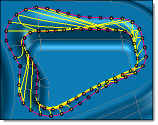
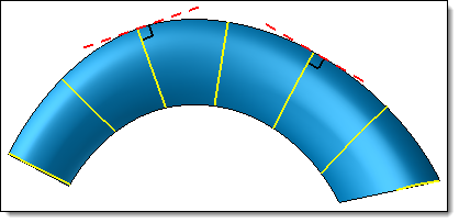
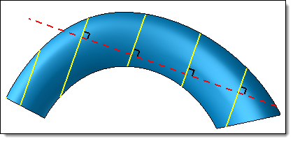
Use tangent as planes normal direction: option available with One guide profile mode only. With this mode, to know the normal of section plane TopSolid uses a tangent on the guide profile on each points. Unchecking this option this normal can be replaced by a direction that will be the same for each points.
|
|
Checking the option, TopSolid uses a tangent on the guide profile on each points (here the used guide profile is the external edge of the shape) |
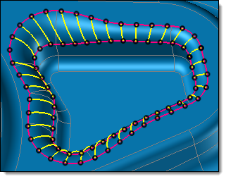
Unchecking the 'option, all sections are normal to the profile used as fix direction (here the red dotted profile) |
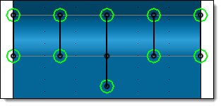
Gudie profiles with preexisting set of points: preexisting points allow to control and modify the exact position of each section.
Selected guide profiles and make sure directions are the same on all profiles.
Selected the preexisting set of points on the profile (equivalent to sections count). These points can be explicit points, serial points or seedling on profile.
Use tangent as planes normal direction: option available with One guide profile mode only. With this mode, to know the normal of section plane TopSolid uses a tangent on the guide profile on each points. Unchecking this option this normal can be replaced by a direction that will be the same for each points.