Fitting


Links / Videos :


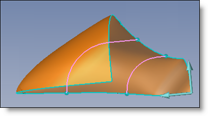
This command allows to create a surface from a set of profiles and possibly with guide profiles and passing points.

This kind of construction is a timesaver to build shape as guide surface for machining.


Creation stages / Use:


Select the Surface > Fitting... command from the drop-down menu.


  1. Select profiles to use.

  2. If necessary add guide profiles.

  3. Validate.


Profiles can come from a sketch, sketch segment, edge or result of multiple intersections.


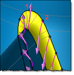
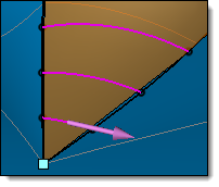
Selecting each profile, an arrow indicates its direction. This direction must be the same for all profiles.

If you are selecting multiple intersections as profiles, TopSolid will not display this direction on each profile. So you cannot control it is the same for all. However, if the command is in error after selecting the multiple intersections you can explode these profiles and control the direction (for that, right click on the multiple intersections available in the Profiles field and select Explode).

If directions are not the same (this is possible in high curvature area), you can:

  • Modify the direction manually on the concerned profiles.

  • Cancel this dialog and increase the points count into the multiple intersections command. Indeed, the direction is chosen according to previous profile and increasing the points count will make profiles closer improving direction compute.


After having explode the multiple intersection we see that direction is inverted between profile 1 and profile 2


Available options:


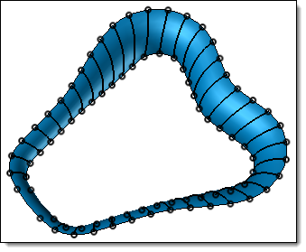
This option allows to create a periodic loft, turning back on itself. TopSolid links the first and the last section.


Unchecking the option

Checking the option


These options allow to build a shape whose ends are points.


Unchecking the option

Checking the option


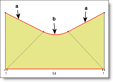
The synchronization represents the way TopSolid make the section correspond with each other.


  • Free: this test mode adapts sweeping best between section using a combination of various methods.


  • Arc length: when you use curvilinear synchronization for the sweep, this means that when the shape is created, the sweep on the curves in done in proportion to the length of each one.


  • Local: when you use parametric synchronisation for the sweep, this means that when the shape is created, the software tries to correspond to the nature settings of the sections.


Example:

The parametric extension for a line is [0;1] (length)

The parametric extension for a circle is [0;360] (angle)


a: Line : parametric extension [0;1]


b: Arc: Parametric Extension [0;54]


  • With the local and arc length modes, the edges of the obtained surface are created by approximation with some BSpline (curve), by following either the curvilinear abscissa either the reference profile arc length.


  • With the free mode, TopSolid does not use the approximation with BSplines to ensure that the simplification (fiting advanced option) gives better results.

Only exceptions where the approximation is used in free mode:

    • In the profile/profile correspondence if the number of profiles segments is different.

    • In the point/point correspondence if the number of segments between consecutive points is different.


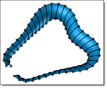
If you check this check box, then the lofted shape will be surfacic and open at its extremities.


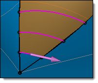
Guide profiles constrain the shape to evolve along these profiles between sections.

The direction displayed on these profiles must be the same.


This option allows to extend edges of the shape at its ends.

Enter the extension value manually.


Different types of correspondence are:


  • Profile to profile: During the shape creation, TopSolid overall matches profiles regarding their built settings (example: a circle is parameterized by an angle). It is the default mode, it usually gives satisfying results.


  • Segment to segment: During the shape creation, TopSolid tries to match two by two segments of each profiles. The result is a surface for each pair of segments. This option is only available when profiles have the same number of segments.


  • With the profile to profile correspondence, if you select guides curves, the synchronization will be applied by section (by intersection between guides curves and profiles defining correspondence points).

  • With the segment to segment correspondence the user has to check that guides curves don't intersect the correspondence.


Minimal division of faces. This mode allows you to smooth the section and the path in order to obtain the face minimum on the resulting form.

Division of the faces into columns, according to the segments of the section. Only the path is smoothed in order to obtain faces for each segment of the section.

Division of the faces into the grid, according to the segments of the section and of the path. . No smoothing is performed, and a face grid is generated by the segments of the section and the path.


This option allows to smooth or not the derivation magnitude between profiles.


  • Single: the derivation magnitude is alone.


  • Smooth: the derivation magnitude is smoothed between profiles for a more aesthetic result.


This option simplifies the geometry of some surfaces.

By default, surfaces from this command are b-spline surfaces. According to the reference profiles, some surfaces could be simplified into planar, cylindrical or conical surfaces.