Distribution
|
Distribution |
This command allows to distribute components along a line in an assembly document.
For example, you can use this command to distribute partitions into an open-space, a handrail and its supports or drawers into a cabinet (distribute 3 drawers by specifying the height of one of them for example).
Creation stages / Use:
Select the Modeling > Distribution... command from the drop-down menu.
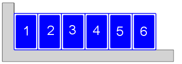
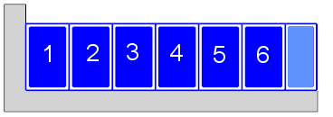
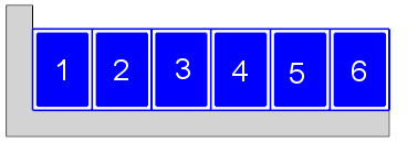
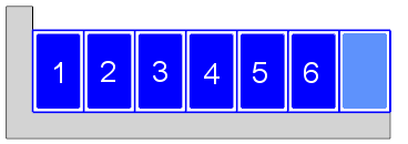
It is possible to distribute up to two components at the same time. The components will be included alternately. The first component always appear at the start and the end of the line. So the first component has always one more occurrences that the second component.
One of the component can be a blank space; which allows to get an alternating of a component and a blank space with a given length.
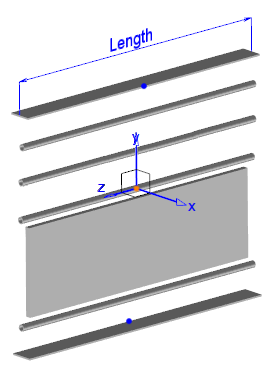
For each component, you can set its length, its position according to the line and its family code as well as the drivers of the component.
The provided length represent the base length along the line. This value is a reference length that will vary according to the settings and options used.
In an assembly document, click the icon or select
the command Modeling > Distribution...
command from the drop-down menu.
|
The components that can be used with this commands are family document from distributable part document or assembly. The generic documents of these family documents must provide the function Distributable component and the family documents must provide the driving Distributable family (by using the command "Tool>Provide Driving"). This driving is available into the library " TopSolid>Components>General ".
|
Available options:
Distribution:
|
|
Distribution mode:
|
Two distribution modes are available:
The "distribute" mode can result in an empty gap at the end (a remainder) too small to be filled with an additional component. While the "mark out" mode never gives remainder.
|
First component:
|
The first component can be:
For each component, you can set its length, its position according to the line and its family code as well as the drivers of the component. The provided length represent the base length along the line. This value is a reference length that will vary according to the settings and options used.
Sub Components: This button allows to access to the sub components configuration windows (see Sub Components) To get access to these settings, you must have activated the advanced option "Substituable in upper level" while assembling the consituents of this component in the generic document.
|
Second component:
|
The second component has an additional mode:
|
First / Second component positioning:
|
These two rubrics allows to define the initial positioning of the first and second component.
|
Advanced Options:
|
This option describe the way the component are ordered along the line:
With the Distribute distribution mode, the following options becomes available:
With the "Distribute" mode, you may get a remainder (empty gap). This option allows you to specify if this remainder must be at the end, at the start or distributed on both extremities of the path line.
It is possible to decide how you manage the remainder:
If you distribute two components, and the remainder is distributed (Distribute remainder or Distribute one more), you can choose to alter the first component, the second or both.
Remainder spread mode: When you alter the length of both component, you can add or remove either an equal value of length on both component or a proportional length value according to the reference length given for each family component.
|
Modifications / Additional information:
Distributing an articulated component, a positioning operation is automatically added so that the articulation can be played.
In the graphic area, a numbered label is created for each occurrence of the components. You can drag these labels (using drag and drop).
In the contextual menu that appear on a label, you have access to the commands "Exception" and "reset position" (if the label has been moved). It is also possible to start the command Exception if you double-click on the label.
Exception:
This command open a dialog box that allow to replace this specific occurrence. You can replace the family by another, replace a blank space by a family, change the code or drivers of the family,...
If you want to change the length without changing the family, you must give the length value and leave the family list empty.
You can replace a family by a black space: select the black space option and give the length if you want a specific dimension, or leave the length field empty to keep using the reference length.
Modify an occurrence:
If you need to modify the geometry of some occurrences (drilling, pocket, trimming,.....) you need to convert them into local part as you would do for a repetition.
The creation of a component that can be used with this command follow the same conception method as any other common parameterized component.
To make this component available into the family list of the Distribution command, you need as well to:
Provide the function "Distributable component" into the generic document (part or assembly) of your component.
|
On this function, you need to provide the following publications:
|
Provide the driving "Distributable Family" into the family document of your component by using the command "Tools>Provide driving"