To be able to use the extruded bars, it is essential that the libraries required for the project be referenced beforehand. The referencing is done via the Add reference contextual command from the references icon in the project tree.
|
Extruded bar |
This command positions the extruded bars in the assembly.
Creation stages / Use:
Select Modeling > Extruded Bar... command from the drop-down menu.
|
To be able to use the extruded bars, it is essential that the libraries required for the project be referenced beforehand. The referencing is done via the Add reference contextual command from the references icon in the project tree. |
Select a type of extruded bar in the drop down list.
Select the code of the extruded bar in the drop down list.
|
This command allows you to position an extruded bar on each selected edge, segment, profile or face.
|
|
This command positions the extruded bar by selecting its 2 end points. |
|
This command positions the extruded bar on a frame and indicates its length. |
|
This command allows to position the extruded bar by constraint positioning.
|
|
This command allows to position the extruded bar on a segment and generates a section view by automatic box as well as a zoom on it.
|
Enter the orientation of the extruded bar. The orientation is a rotation around the longitudinal axis.
Check or uncheck the Reverse extruded bar. This option reverses the direction of the extruded bar.
Select the offset type by clicking one point in the extruded bar preview of the dialog. The selected point becomes blue. The longitudinal axis of the extruded bar will be on this point. It can also be changed by double-clicking one of the yellow points (in the graphic area)
If required, enter the value of the horizontal offset.
Select the type of vertical offset from the drop down list.
If required, enter the value of the vertical offset.
Positioning help:
|
Three icons in the top right-hand corner of the graphics area can be used to facilitate profile positioning (features available for all installation modes except the constraint installation mode). The graphic cut is ephemeral, which means that if the user changes positioning mode, or if the user quits the extruded bar dialog, then the cut view is deleted and the initial graphic configuration is restored.
|
|
The ephemeral cut box dialog opens, allowing you to configure it (dimensions, color, etc.). Ephemeral box cuts are always initialized with values that ensure the box to be centered and of a size close to that of the installed extruded bar. |
|
Cut by box: This icon allows to activate/deactivate the previously created cut. |
|
Focus on section: This icon allows to modify the graphic view to be focus on the cut section (normal to the XY plane of the cut by box). |
|
|
|
|
|
|
Advanced Options:
Substituable in upper levels:
This option allows to authorize the substitution (replacing) of the extruded bar when the assembly document is included into another assembly. When it is not checked, the extruded bar will be greyed in the substitution dialog box. See the sub-component substitution command for more details. |
Part creation method:
|
|
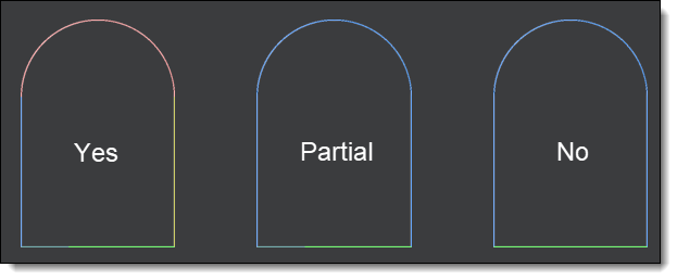
Profile decomposition:
This menu allows you to choose how to decompose an extruded bar when placing it on a profile:
|
Modifications / Additional information:
To modify the type of extruded bar, its offset, its orientation, use the Edit contextual command.
The extruded bar family can contain drivers to be able to modify them during extruded bar inclusion.
An extruded bar can be an assembly to allow to manage a different material for each part of the assembly as for example a extruded bar with a seal.
During the in place edition of an extruded bar, it is possible to associatively hang on the assembly.
The Replace contextual command allows to interchange several extruded bars at the same time.
Operations on extruded bar:
When an extruded bar has operations other than miter trim, main trim or planar trim, it is identified by a specific management operation in Analysis stage with a parameter Operated = True in Parameters > System Parameters folder of the Entities tree. This parameter can then be retrieved in a bill of material, allowing the user to make a more detailed drafting of these extruded bars.
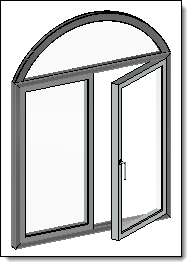
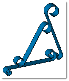
Curved extruded bar:
|
|
|
|
Extruded bar components can be included on 2D or 3D sketch with splines or arcs. Into a sketch, tangent curves will create a single curved extruded bar. |
|
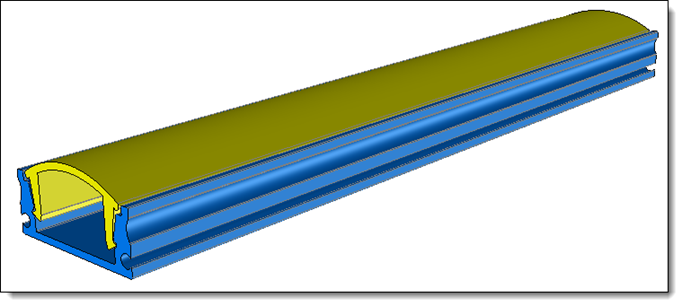
Extruded of extruded bars:
In an assembly document, it is possible to included several extruded bars and to provide the Extruded bar function document in order to define an extruded bar of extruded bars. This allows for example to create an extruded bar with its seal. This extruded bar behaves like any part extruded bar and supports cutting operations (miter trim, main trim, curved extruded bar, ...).
|
|
|
Example of extruded bar made of 2 extruded bars. |