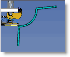
Center of Mass Trajectory
|
|
Center of Mass Trajectory |
This command allows to calculate and visualize by a 2D or 3D sketch, the center of mass trajectory of several rigid groups during a simulation. This command specially allows to see if a simulation center of mass is limited in its supports.....
Creation stages / Use:
Click the icon or select the Simulation > Center of Mass Trajectory... command from the drop-down menu.
Select the simulation.
Click Refresh if the button is not grayed out. The button is grayed out when the simulation is updated. Refreshes can also be run from the entities tree.
Select rigid groups to take into account.
Select the type of sketch to generate. If this is a planar sketch, select its plane. If this is a spatial sketch, there is no plane to select.
Validate by clicking  .
.
|
|
|
|
|
A trajectory is a polyline. The number of points is defined in the simulation, by the number of points per second. The greater the number of points, the more exact the trajectory, but the calculation time will also be longer. |
Available Options:
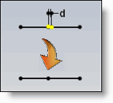
Basify:
|
|
The trajectory can be either associative, and therefore recalculated when the mechanism is changed, or by checking Basify, produce an editable sketch at the modeling stage that may be used. |
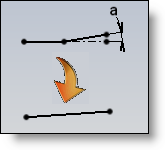
Advanced options:
|
|
|