
Flange
|
|
Flange |
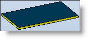
This command adds a linear part to a sheet part utilizing the length of one of its edges..
Creation stages / Use:
Click the  icon or select Sheet Metal > Flange... from the drop-down menu.
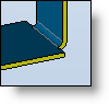
Select the flange edge
|
|
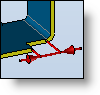
Click yellow handles for a rapid and dynamic modification of the length and the angle of your flange. |
|
|
Double-click the labels to enter the length and angle values of the flange. |
(several edges can be selected to create several identical flanges).
Enter the bend parameters (inner radius, angle, position).
Enter the length of the flange.
Enter the width of the flange.
Indicate the parameters of the notches.
Validate the creation of the flange with the  button.
|
|
Click yellow handles for a rapid and dynamic modification of the length and the angle of your flange. |
|
Double-click the labels to enter the length and angle values of the flange. |
Available Options:
Bends:
|
|
This section allows you to define the bend parameters:
|
||||||||||||
|
|
|
|
|
When the reference face of the flange (face used to calculate the angle) is cylindrical, the Thickness on the edge mode and Thickness under the edge are not functional. |
Length:
|
|
This section defines the length of the flange:
|
|
|
|
|
|
|
|
|
|
|
|
|
|
|
|
|
|
|
Width:
Notches:
Advanced options:
|
|
When the flange is made on several edges, you can indicate a gap for the auto-trim of the flange:
|
|
|
By activating the Create sketch option, TopSolid creates a sketch (rectangular) for each flange, you can then modify the shape of the flange by editing the corresponding sketch. |
Modifications / Additional information:
When the flange is created, a double click on one face of the flange displays the main driver dimensions (length, angle, inner radius, width, etc.).


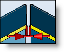 This gap corresponds to the width of the slot where the flanges should intersect.