This section defines the width of the flange:
-
Select the calculation mode of the width:

-
No shift: The width of the flange equals the length of the edge.

-
Symmetric shift: The flange is centered on the middle of the selected edge.

-
Start and end shifts: The arrow drawn on the selected edge indicates the direction for entering the offset values.

-
Start shift and width: The arrow drawn on the selected edge indicates the direction for entering the offset and width values.

-
Width: The flange is centered on the middle of the selected edge.
-
Enter the values of offset and/or width of the flange.
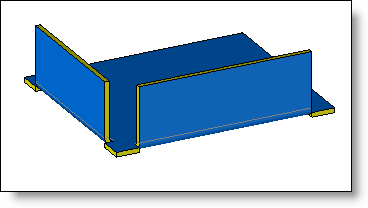
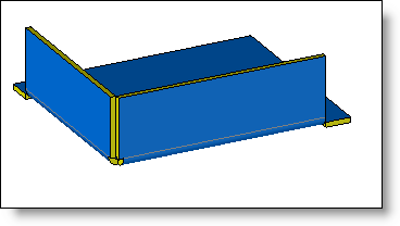
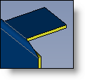
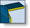
The option Close neighbor borders allows, when several edges are selected, to have borders joined together. In this case, the entered offset is not taken in account.
|
|
|
|
Without Close neighbor borders option |
With Close neighbor borders option |
-
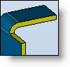
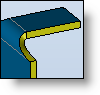
Select the type of bend transition:

|
|
|

|
|
|

|
|
|

|
|
|

|
|
|

The Release bends extremities option allows to operate neighboring bends of the selected edge to allow the creation of the flange bend under construction.
This option is specially useful when creating a flange with the "thickness under edge" mode.
When the Identify corners relief is checked, corners relief of these flanges will be automatically extracted when creating the unfoliding document.
-
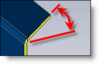
Start and end angles: by default lateral edges of bend or flange are perpendicular to the support edge, but by entering angle values, it is possible to modify them.
|
|