Slot:

Tongue:

|
|
Slot or Tongue |
This command creates a slot or a tongue on a shape by running a section along a path.
Creation stages / Use:
Select Shape > Other Operations > Slot or Tongue... command from the drop-down menu.
Select the type of operation you wish to carry out.
|
Slot: |
|
Tongue: |
|
Select the path of the slot/tongue
Select desired slot/tongue template or the sketch created for this purpose in the document to define the section.
Enter dimensions of your slot/torque or select a code.
Available Options:
Slot or tongue:
|
|
Here, select the type of operation to be carried out and select the shape to modify.
|
Path:
|
|
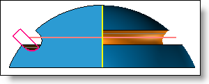
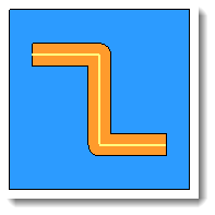
The path represents the route following by the slot/tongue. It can be open or closed. By clicking the "+" it is possible to create an edge profile "on the fly".
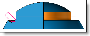
Planar path:
The sketch tool is always oriented based on the plane of the path sketch. It is therefore important to correctly orient the plane of the path sketch in order to obtain the desired slot/tab. Generally, the plane of the sketch must be parallel or tangent to the operated face.
When using an edge profile, if only a linear edge is selected, the boundary will be invalid. A line does not define a plane.
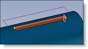
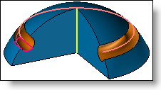
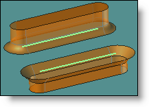
Path with tilted tool:
When you use path on which you need to use a tilted tool, you need to specify a reference direction so the orientation of the tools remains correct all along the path. On the example bellow, the tool sketch is titlted according to the path.
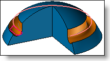
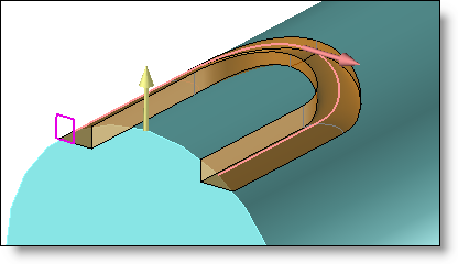
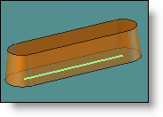
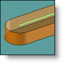
Non planar path:
When the path is not planar, it is necessary to specify a direction that define the orientation of the toll along the path. In the example below, the direction is shown with the yellow arrow.
|
Sketch Tool:
|
|
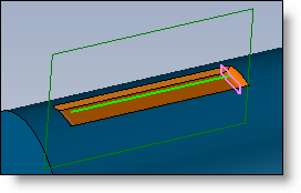
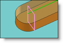
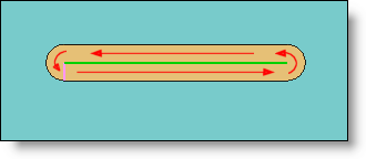
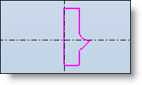
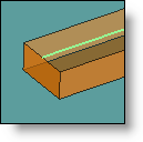
The sketch tool is actually the section of the semi-slot/tongue and runs along the path in the following way to generate the shape of the operation:
The path is in green, the sketch tool in pink and the resulting geometry in orange.
User sketch: If you wish to use a sketch created in the document as a section of your slot/tongue, you need to define it with the following criteria:
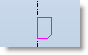
Sketch for slot:
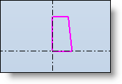
Sketch for tongue:
Double-usage sketch:
Template sketch: By checking this option, you can use a sketch template. The drop down list offers you the available slot/tongue templates in the referenced libraries.
If the selected template has pre-defined dimensions by virtue of a catalogue, you can select the desired dimension code.
|
Drivers:
|
|
In the event of a sketch template, if the template has dimensional drivers, you can fill them in here. The name of the drivers and their number may vary based on the template selected. |
Advanced options:
|
|
These options enable you to modify the geometry of corners and extremities:
|
Modifications:
If a sketch template was used, once the function has been validated, a sketch is created with the dimensions of the slot/tongue in place.
Therefore, to modify the geometrical dimensions of the operation, you need to edit the sketch.
Additional information:
|
|
You can create customized slot/tongue templates. |