Groove or shoulder
|
|
Groove or shoulder |
This command creates grooves or shoulders on cylindrical or tapered shapes. The geometry achieved is linked to the choice of a groove/shoulder template from the referenced library
|
|
Before being able to use this function, your project references must have a library containing grooves/shoulder templates. The "TopSolid Mechanical Library" contains a selection. |
Creation stages / Use:
Click the icon or select Shape > Other Operations > Groove or Shoulder... command from the drop-down menu.
Select the type of operation you wish to carry out.
|
Groove: |
|
Shoulder: |
|
Select the desired groove/shoulder template.
Enter dimensions of your groove/shoulder or select a code.
Define the positioning of the operation.
Available Options:
Template:
|
|
The drop down list proposes the groove/shoulder templates available in the referenced libraries.
If the template selected features pre-defined dimensions due to a catalogue, you can select the desired dimension code. |
Drivers:
|
|
Here, you can define the dimensions of your groove/shoulder.
Offset: this value refers to the depth/overthickness of the groove/shoulder.
Width: this value refers to the width of the groove/shoulder. |
Position:
|
|
This option determines the position of the operation.
Axial frame: if the mouse is rolled over a cylindrical face, an axial frame is displayed dynamically. Click here to create the frame.
Reference plane: this option changes the reference plane/face for measuring the positioning distance of the operation.
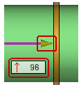
Once the frame is created, the distance of the frame in relation to the reference face can be modified by pulling on the point of the arrow or by double-clicking on the label to modify the value.
Face mode:
Diameter mode:
Reverse: This option reverses the direction of the groove/shoulder in the event the operation is not symmetrical (a fillet on only one side, for example). |
Modifications:
Once the function has been validated, a sketch is created with the dimensions of the groove/shoulder in place.
Therefore, to modify the geometrical dimensions of the operation, you need to edit the sketch.
If you wish to modify the positioning of the operation, you can either edit the axial frame or edit the operation itself.
In the event you edit the operation, a check box called "Replace the template" allows you to fully redefine the template of the groove/shoulder.
Additional information:
|
|
|