Creating a groove or shoulder template
|
|
Creating a groove or shoulder template |
This page explains in detail how to create a groove or shoulder modal which can then be used in the Groove or shoulder function.
Principle:
When using the Groove or shoulder function, TopSolid proposes a list of templates for this operation. These templates come from the libraries which are referenced in the project.
Therefore, if you wish to use a personal template, this needs to be created in the personal library.
In the personal library, two documents need to be created:
A 2D modeling document: this document shall contain a geometrical representation of the section of the groove/shoulder operation and the dimensional parameters.
A Family document: this document shall contain the lists of the drivers linked to the dimensional parameters and, if required, a catalogue of dimensions.
Creation stages / Example:
Here are the stages to be followed including a real example.
We shall create a centered groove/shoulder template with fillet
2D modeling document:
In your personal library, create a new "2D modeling" document and name it "Centered with fillet" (for example)
This document can be filed in a folder of any name.
Start a sketch
|
|
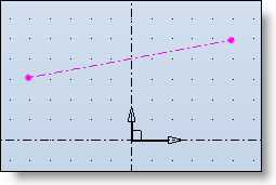
The X axis of the frame symbolizes the axis of the cylinder or taper support of the operation.
Create an inclined line symbolizing the silhouette of the cylindrical or tapered face support of the groove/shoulder.
Define this line in construction and external .
|
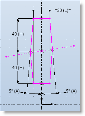
Model the section of the groove/shoulder on each side of the inclined line.
|
|
The upper part shall be used to generate a shoulder.
The lower part shall be used to generate a groove.
In our example, we shall use three dimensional parameters:
W: represents the width of the groove to the back OR the width of the shoulder to the vertex
H: represents the depth of the groove OR the height of the shoulder measured in its center
A: represents the draft angle |
Save the document put in vault.
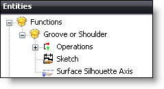
To be able to use this template in the "Groove or shoulder" function, the relevant functions need to be added to our document.
|
|
To do this, you need to:
|
Each function now needs to be linked (the sketch and the axis) to the relevant geometries in the document.
|
|
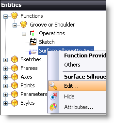
To do this, you must edit each function to allocate the relevant geometry to it:
For the axis of the silhouette surface, you must select the inclined line created right at the start.
For the sketch, you need to select the sketch created previously in this same document. |
Save the document and check in.
Validate the document (Right-click > Life cycle).
Document Family:
The document will enable y to determine the dimensional driving of our operation.
There are two ways of inspecting the dimension of the geometry:
by the drivers: the values of these driver parameters are then requested when the template is used
by a catalog: the dimensional choice of the parameters defined in the catalogue is done via a dimensional code list.
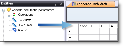
In your personal library, create a new "Family" document
From the personal library tree, "drag and drop" from the 2D modeling document into the graphic zone of the Family document.
|
|
From here, one or more of the dimensional inspection methods can be used (driver or catalogue) or both may be combined. However, a parameter may not be in both drivers and catalog. In our example, both possibilities are explained supposing that one of them is used for all the parameters. It is up to you, then, to select the one you wish to use (or if you wish to combine both). |
Using the drivers:
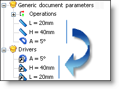
In the entities tree in the Family document, drag and drop the Parameters of the generic document to the Drivers folder.
|
|
In our example, we can attribute the following descriptions: A: Draft angle W: Width H: Depth/Height
|
Check in and validate the Family document
Using a catalog:
In the entities tree of the Family document, "drag and drop" the Parameters of the generic document to the parameter table.
|
|
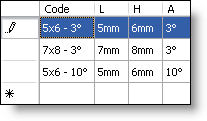
Then complete the catalog with the panel of desired dimensions for each dimension code.
The "Code" column is the list which will be displayed when the template is used to determine the set of values of the parameters defined in the table. |
Check in and validate the Family document.

 You may specify a description for each driver by editing them in the entities tree. This way, when using this template, the description will be displayed in the dialog rather than the name of the parameter which is not always explicit.