Main trim
|
|
Main trim |
This command creates a main trim on extruded bars. The first extruded bar will extend to the first planar face on the tool extruded bar .
Creation stages / Use:
Click the icon or select Modeling > Main trim... command from the drop-down menu.
Select extruded bars to modify.
Select the tool extruded bar.
Check Use Closest Plane so that the first plane of the tool extruded bar encountered is the trimming plane, otherwise the furthest plane is used for trimming.
Enter the offset between the 2 extruded bars.
|
|
|
|
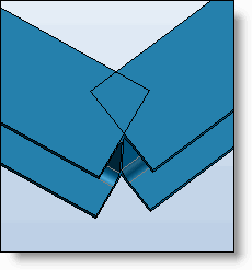
Extruded bars before the main trim |
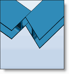
Extruded bars after the main trim |
|
|
|
|
|
Contrary to the tabs cross section, only profiles with the same tool extruded bar must be selected.. |
Modifications / Additional information:
The Create folder option groups all cuts (when several profiles are selected) in a folder of the operations tree.
The modification of the main cross section is performed contextually from the operations tree or on the edge from the graphic.