Automatic Tube Nesting


Links / Videos :


This command allows to automatically place several Tube type parts on a support by entering the quantity of each part.


Creation stages / Use:


Select the Nesting > Automatic Tube Nesting... command from the drop-down menu.


  • Save: This option allows to save settings. The nesting operation is created but it is not computed and assemblies documents are not created.

  • Recompute: The position of the already nested parts will be recalculated by taking into account the added parts. It is possible to increase or decrease the part quantity, as well as the degrees of freedom, the security gap.


  1. Activate the Parts tab. Drag the parts to nest from the project tree.

  2. Activate the Supports tab. Drag the supports to use from the project tree.

  3. Choose the strategy.

  4. Choose the options.

  5. Validate.


This command is protected by a license.


The parts are placed according to the X axis of the reference frame defined by the Extruded Bar Nesting Characteristics command.


The nesting window is composed of six tabs:


This tab allows to select the parts to nest by dragging them from the project tree and by filling the placing informations (quantity, rotation, ...)

  • Parts are added by drag/drop:

    • of part documents into the parts list dialog.

A part can be placed if it follows these rules:

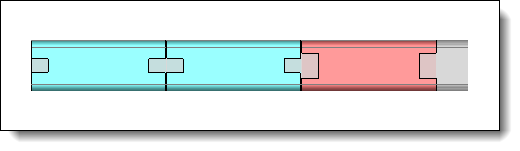
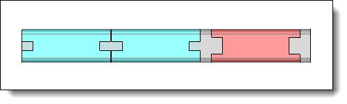
  • The document provides the Nesting Tube Component function. To do it, use the Extruded Bar Nesting Characteristics command.

  • The detailed representation contains only one shape.

    • or BOM. It allows you to:

    • Nest unbendings associated with parts in the BOM, rather than the parts themselves, taking into account the quantities of parts.

    • Nest local parts of an assembly.

    • If the BOM contains manufacturing indexes, these are transferred to the parts in the documents produced by the nesting.

  • The quantity of each part to nest can be modified. If after the calculation, a quantity is highlighted in orange, it means that the asked quantity has not been placed.

  • Priority: The nesting  takes supports with a priority of 1 (the smallest value) and places parts regarding their priorities. Then supports with priority 2 are completed with residual parts, always by considering their priorities. And so on....

Parts and supports priorities are independently considered.

  • Allow flip:

This option allows to flip the part on the support in order to gain in loss rate (on the X axis of the reference frame).

Into the nesting document, part quantity is global (flipped part or not).

  • The Degrees of freedom are allowed rotations of the part.

Free: The nesting manages the part rotation from 0° to 360° with a step of 1°.

Interval: The option allows to enter a minimum angle, a maximum angle and a rotation step. During the nesting, the part could be rotated regarding this entered step. If the minimum angle is 0°, the maximum angle is 360° and the step is 90°, the part could be rotated at 0°, 90°, 180°, 270° or 360°.


This tab allows to define the list of supports to use to nest parts and the nesting characteristics (quantities, border gaps).

  • Supports are added by drag/drop of part documents from the project tree into the supports list dialog. Use the Extruded Bar Nesting Characteristics command and select the Support mode.

  • Possibility to specify border gaps with different values on the left and on the right.


This tab summarize the contain of each placing. It displays the number of included support ( a support can be included several times if the parts quantity allows it) and the loss rate.

This tab is only displayed if the nesting has been calculated.


This tab allows to manage the nesting strategy.

  • Packing: Allows to define if the nested parts are on the left, on the right, on the top or the bottom of the support.

On the left: The packing is realized on the left of the support, the loss area is on the right.

On the right: The packing is realized on the right of the support, the loss area is on the left.

  • Cut gap: Gap between each part on the support.

  • Common cut: Allows to group together parts whose flat length of the section at the ends is the same (perfect) or partial (allowed deviation 50%).


Perfect matching common cut

Only identical sections use common cut gap

Partial matching common cut

The length difference of the sections (flat) does not exceed 50%, all the parts use the common cut gap

Partial matching common cut

The red part having notches on all sides, the length difference of the sections (flat) is greater than 50%


The check of the consistency between the material of the part and the support can be activated. If it doesn't match, the nesting can't be validated.

It is possible to allow supports and parts without material. In this case, there will be no error.

  • The check of the consistency between the thickness of the tube and the support can be activated.

  • The Check quantity respected option allows to ensure that the requested quantity is respected.

  • The Invalid if a problem is detected option makes the document invalid if one of the strategy criterion isn't coherent (wrong quantity, material, thickness, ....)


This tab allows to manage colors, default values for border gaps between parts and supports, for the gap between supports, the text style to use and the template to use. These defaults values and options allow to fill the new documents dragged in this nesting.

      • The Automatic colors allows to assign a random color to each different part.

      • The different gaps for all new dragged supports in the supports list can be filled with a default value.

      • The gap between supports can be filled by default.

      • The nesting text style can be selected or created. It is the text displayed in the nesting which indicates for example the loss.

      • An assembly template can be used. A nesting generates documents like assemblies, manufacturing, sheet metal manufacturing, ....) with a document by support and nested parts. The selected template will be used when creating the document.


Modifications / Additional information:


To use a symmetrical part a Mirror part must be created and it must be added to the parts to nest.

When creating the mirror document, the Nesting characteristics analysis operation is derived too with the rules below:

  • For part or support:

  • When section to nest is manual in the reference document, it will switch to automatic in the mirror document.

  • For part only:

  • If there is a security area defined with manual section in the reference document, TopSolid will not use security area in the mirror document.

  • If part uses freedom degrees they will be managed in the mirror document. When freedom degrees have been set from a fonction provider Tools > Fonctions > Provide fonction > Nestable component freedom degrees..., they will be saved if fonction derivation is checked in the derivation operation.