 icon or select the Tools > Nesting
Characteristics Management > Extruded Bar Nesting Characteristics...
command from the drop-down menu.
icon or select the Tools > Nesting
Characteristics Management > Extruded Bar Nesting Characteristics...
command from the drop-down menu.
|
Extruded Bar Nesting Characteristics |
This command allows to specify the nesting properties of a part or support for extruded bar nesting. This command is available in Part and Assembly. These characteristics are used by the Automatic Tube Nesting and Automatic Bar Nesting commands.
Creation stages / Use:
Click the
icon or select the Tools > Nesting
Characteristics Management > Extruded Bar Nesting Characteristics...
command from the drop-down menu.
Choose if you wish to define the characteristics of a extruded bar to nest or the characteristics of a support that will contains extruded bars to nest.
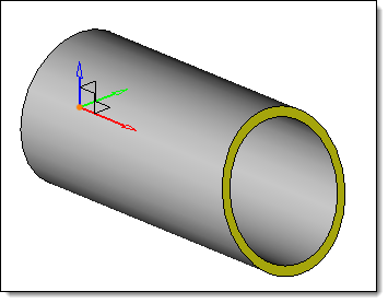
Select the reference frame (its Z axis must be the extruded bar axis).
Select the type of rotations allowed.
Validate  .
.
|
The Z axis of the reference frame in the same as the extruded bar axis |
|
This command is protected by a license. |
|
|
Available options:
Tube Nesting Characteristics:
|
|
Freedom Degrees (Part mode only):
|
It is possible to modify the freedom degrees by ticking the box:
|
Advanced Options:
|
|
Modifications / Additional information:
A Extruded Bar Nesting Characteristics Management operation is created in Analysis Stage.


 Free:
Free: Interval: