Bended Shape Positioning


To define a bending step, it is necessary to define the two configurations of the part in this step: the positioning of the part "after bending" (i.e. after the current bend has been made) and the positioning of the part "before bending" as well as the positioning of the backgauges.


This command allows the shape to bend to be positioned in the machine after bending.


Creation stages / Use:


Click the  icon or select Bending > Bended Shape Positioning... command from the drop-down menu.


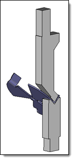
  1. Position the shape to bend on the machine by its bend face and a selected edge on the backgauge side.

  2. Select the die(s) and punch(es) to make the fold.

  3. Position the part according to these tools.

  4. Validate .


The Bending operation command is chained automatically if the Automatic Next Bending Command mode is activated.


Available options:


  • Bend face: Select the face of the bend to treat.

  • Edge backgauges side: Select an edge to orient the part on the machine. This edge will be positioned on the backgauge side.

  • Hide part: It is possible to hide the shape to bend once the bend to be processed has been selected. This makes the shape between the punches and dies easier to position, leaving only the preview of the positioned shape displayed.


This section is used to select the die(s) used to create the bend. Two selection modes are available:

  • Tools: This mode is used to select Die tools included in the bending machine.

  • Dies: A selection filter makes it possible to take only Die type tools.

  • Manual: It is possible to define a die by its characteristic values. This is an advanced mode, allowing to quickly implement an undefined die in the libraries.


  • Punches: This section allows you to select the punch(es)  used to create the bend.

  • A selection filter makes it possible to take only Punch type tools


This section allows the bend to be positioned laterally between the punches and dies.

  • Reference: This option allows you to choose to align the bend either in relation to the Punch or in relation to the Die.

  • Base position:  This option allows you to determine how the bend is aligned with the chosen reference.

  • Left borders: The left edges of the bend and the reference are aligned.

  • Centers : The centers of the bend and the reference are aligned.

  • Right borders: The right edges of the bend and the reference are aligned.

  • Lateral shift: You can fine-tune the positioning by specifying a positive or negative shift value. The reference chosen is the fixed side.   


The Information area provides useful information on :

  • Bends: Characteristics of the bend

  • Dies : The selected Die(s)

  • Punches: The selected Punch(es).


  • Bending type: It is possible to force the type of bending associated with the operation (a default value can be indicated in the selected Die).

  • Forced: Lists the available bending types.

  • The bending type setting is available in the drawing.

  • Accept collisions: A collision test is carried out between the shape to bend and the selected tools. If a collision is detected, it is identified on the form to bend and prevents the command from being validated.
    If this option is enabled, it is possible to validate the command even if collisions are detected.