Choose the frame
that will orient the block envelope. It is possible to create frame
on the fly with the  .
.
Choose the dimension for each direction to create the block.
Validate with  .
.
|
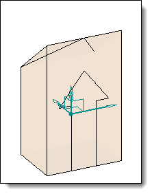
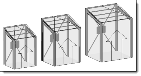
Block Envelope |
This command allows to define block envelope that will be used as geometrical drivers in a family document such as shelves, separator, doors ... In the assembly, this component will be able to position and resize automatically.
See also : Creation and use of Block Envelope
Creation stages / Use:
Select the Construction > Block Envelopes > Block Envelope... command from the drop-down menu.
Choose the frame
that will orient the block envelope. It is possible to create frame
on the fly with the .
Choose the dimension for each direction to create the block.
Validate with .
|
|
|
It is possible to modify directly from the graphic area the lengths of block envelope. For that, double click on the block envelope to show the dimensions. |
Options available:
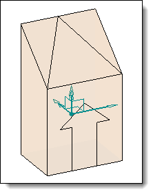
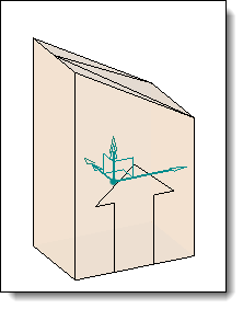
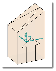
Secondary Z length:
|
This option allows to manage blocks with a slope. The slope can be defined according to the four vertical faces of the block.
|
Advanced options:
|
Create parameters:
Allows to create length parameter for the 3 axis. This parameters will be on the Parameters folder in the entities tree. |
Modifications / Additional information:
From the entities tree, the Descriptions and Default Selection contextual commands allows you to respectively define a description for each dimension of the block and the inclusion type.
You can choose the Automatic mode, pick the front face of the block shell and then switch to the manual mode in order to select other faces.
A block shell is not a shape, modeling operations like fillet, chamfer, boolean,... are not allowed, it cannot be used in a drafting document as well.