Constrained panel (in an assembly document only) :

Select Constrained panel mode.
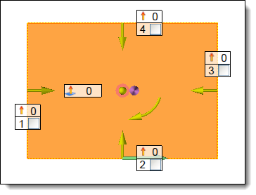
Select face.
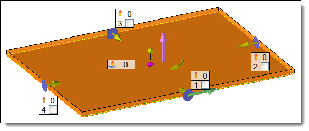
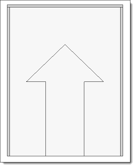
Select orientation.
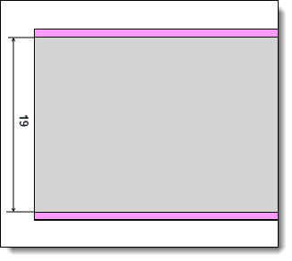
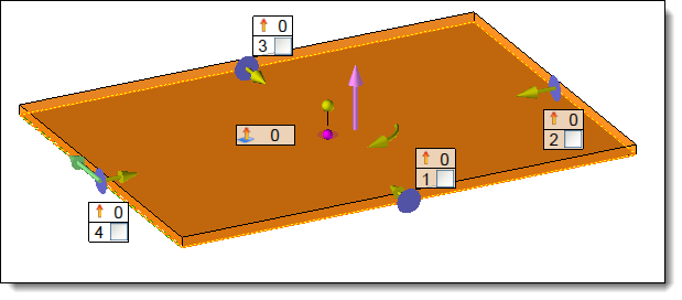
Define offsets.
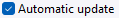
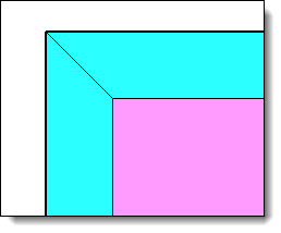
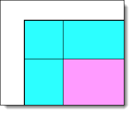
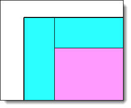
Select panel position relative to face:
|
Panel on profile (in a panel or assembly document) :

Choose or create a profile directly.
Select an orientation.
Select the position of the panel in relation to the profile:
|
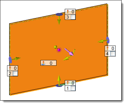
Panel on face (in an assembly document only) :

Select one or more faces. (Select multiple faces to create a panel
panel from several faces)
Select an orientation.
Select the panel position relative to the face:
|