Electrode
|
Electrode |
This command allows you to create the electrode part. This one is included in the electrode document. It is possible, with the same command, to manage the adding of a base.
Creation stages / Use:
Click the  icon or select the Electrode > Electrode...
command from the drop-down menu.
icon or select the Electrode > Electrode...
command from the drop-down menu.
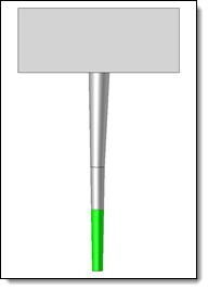
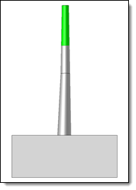
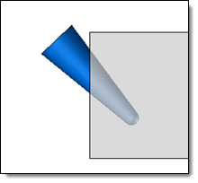
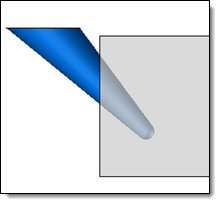
Select the eroding shape(s) which will determinate the electrode and its dimensioning origin.
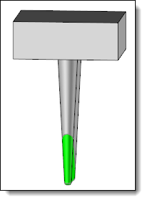
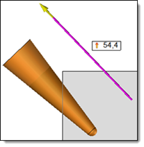
Determine if a base need to be added or not, and its definition.
It is possible to associate a Stock from the library to this electrode.
Validate 
|
This
command is available only in the |
|
|
Available options:
Electrode Creation Management :
|
|
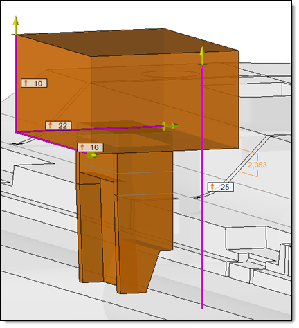
Base:
|
|
|||||||||||||||||||
|
It is possible to associate a stock to the created electrode. This stock will be a Document one in the Electrode file. You can create your own Stock component, with providing the Electrode Stock function.
|
Advanced options :
|
|
Modifications / Additional information:
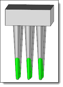
The electrodes created are automatically inserted in the Electrodes set. This set is automatically created in the file if no electrode was created before.
It is possible to edit in place the electrode, or open it from the Project tree.
Repeat an electrode will automatically create the Theoretical positions of this one.
In
the electrode document, the cameras
are associative with the Electrode
Base frame:
|
|
The Front Camera, associated to the XZ+ plane of the Base frame. |
The Electrode Camera, associated to the XZ- plane o the Base frame. |

 Modeling stage


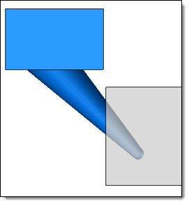
 Eroding shape direction
 Positioning origin direction
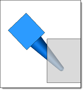
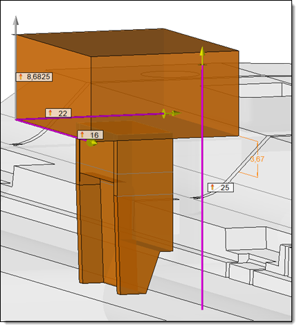


 No base:
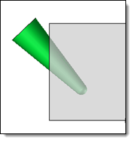
 None
None
 Chamfer