|
Building |
This command allows to create a simplified structure of a building. The construction is defined by a number of levels each containing a floor and walls built from sketches.
Creation stages / Use:
Choose the Modelling > Building... command from the drop-down menu.
There are several steps to using this command:
- The name and description.
- The number of levels and the default ceiling height.
- The type of wall and slab and their properties
- The position of the building
- Advanced options
See the additional information chapter for more details.
- Slab sketch (Level 1)
- Wall sketch (Level 2)
- Slab sketch (Level 2)
- ...
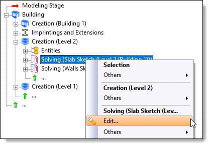
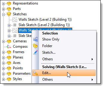
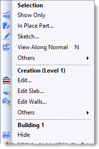
The editing of the sketch of each level component can be done from the operation tree, the entity tree, the entity tree or the context menu in the graphics area.
Available options:
Building:
|
You can give the building its name and description. Levels count: Specify the number of levels the building contains (the ground floor counts as one level). Default height under ceiling: corresponds to the height between the top of the bottom slab and the bottom of the top slab. |
Walls and Slabs:
|
Under these two sections you can choose which wall or slab family you wish to use. The options available for each type of wall or slab depend on the drivers available in the chosen family.
Default thickness: This is the thickness that the walls or slabs will have when they are created. |
Positioning:
|
The position defined in this section corresponds to the position of the first sketch created. |
Advanced options:
|
Imprint walls on slabs: allows the slab to be divided into zones. Thus the edges of the walls generate edges on the upper side of the slab. This can be useful for reclaiming an area or creating a covering quickly.
Extend exterior walls: allows the slab to be masked with the walls. The use is purely aesthetic and does not affect the different dimensions. |
Modifications / Additional information:
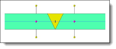
Drawing of wall and floor sketches :
|
The yellow arrow indicates the outside of the wall: the point corresponds to the outside and the base corresponds to the inside. By clicking on this arrow, it is possible to turn the wall inside out. The spheres allow you to change the alignment of the wall in relation to the segment created.
The Wall Properties command allows you to make local or global changes. It is thus possible to modify the thickness, the height, the alignment or even the drivers on the Wall (family) component.
|