|
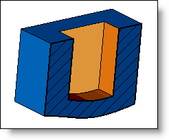
This command allows you to create a pocket on the part having the same shape as the profile used.
Creation Stages / Use:
Click the
icon or select Shape >
Pocket... from the drop-down menu (or Modeling
> Shape > Pocket... in the assembly document).
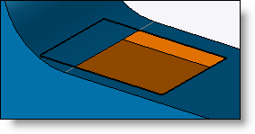
Select the shape to modify.
Select the section to use to generate the pocket. A sketch can be created on the fly by using the "+".
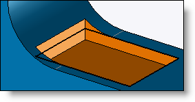
Define, if need be, the recess direction of the pocket (normal to the section by default)
Define the bound of the bottom of the pocket (see available options for the different available modes)
|
If the section is opened, you should first use the Offset command before using this command. |
|
|
Available Options:
Limit:
|
You can define the bottom of the pocket in several ways:
|
Draft:
|
By checking this box, you will be able to add a draft on all lateral faces of the pocket. |
Offset limit:
|
For limits like Point, Plane, Surface, Face set, Shape, it is possible to add an offset.
Example of an offset limit regarding the surface. |
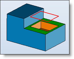
Through over:
|
This option allows you to make the pocket countersink on the material of the part located above the section. This option should be active when the pocket section is mounted on a portion of the part and the area above it must be removed. By activating this option, TopSolid removes the material found directly above and in contact with the section, until it falls off.
|
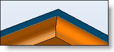
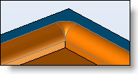
Blends and fillets:
|
Blend: allows to add a fillet or a chamfer on the upper edge of the pocket. It is the edge between the reference face and the pocket.
Fillets: allows you to add fillets.
|
Reference plane:
|
This option allows you to make the pocket on the other planar face, this face must be parallel to the definition plane of the sketch. The depth of the pocket is therefore calculated in relation to the reference plane and not in relation to the sketch.
|
Advanced Options:
Entry point : Once the machining process defined, it is possible to activate this option in order to defined entry points positions for this machining.
Give the diameter value and select the points to define as entry point positions.
The entry points can be displayed/hidden
into the graphic area by using the display mode Create
MF  available in the Edition
menu or on the Home Tab icon bar.
available in the Edition
menu or on the Home Tab icon bar.