The various components of the panel are local parts.
|
Panel |
This command allows you to create a panel.
Creation stages / Use:
Select the Wood > Panel... command from the drop-down menu.
For a Panel document, use the Modeling > Panel command ...
Panel creation by profile (in a panel or assembly document):
Choose or create a profile directly.
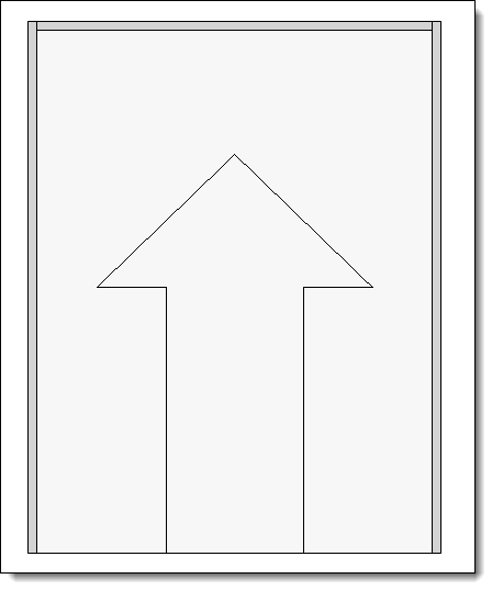
Select an orientation.
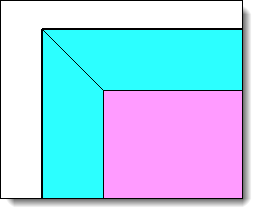
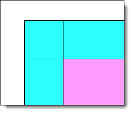
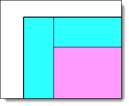
Choose the position of the panel in relation to the profile:
|
|
Creation of the panel by constrained block (in an assembly document only):
Choose to create a constrained block panel or a profile panel.
Choose a constrained block or a profile.
Choose the orientation.
Choose the position of the panel in relation to the profile:
|
|
|
The various components of the panel are local parts. |
|
A panel on a constrained block will make it easier to change its position, than a panel on profile. |
|
It is possible to access the panel control in several ways. Depending on the panel will be positioned differently:
|
||||||||
Available options:
Panel Parameter:
|
Allows you to create a Panel parameter.
|
Material:
|
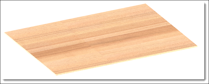
Allows you to define the multi-layer material to be used. Select the material and a code if it comes from a family document.
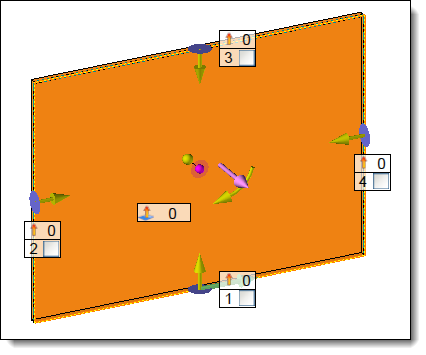
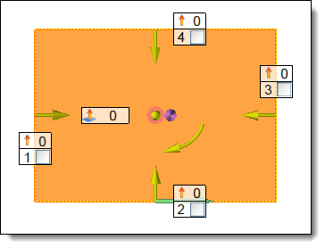
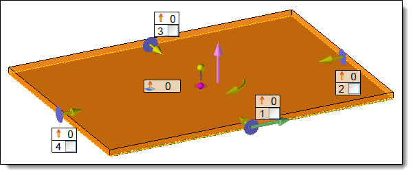
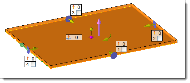
The pink arrow in the center of the panel allows you to reverse the layout of the of the multilayer panel (top and bottom).
|
Edges :
|
Allows you to define the edge family to be used, then enter a code.
Allows you to apply the same family document to all edges. If this option is unchecked it is possible to change the family of an edge
Allows you to apply the same cut to all edges, select the cut from the drop-down menu. It is possible to change the start and end cut of an edge in the table.
The yellow arrow in the center of the panel allows you to move the edge identifiers around the panel. Right-clicking on this arrow reverses the direction of rotation. This arrangement is important in the case of the realization of a box with panels of the same dimensions.
|
|||||||||
|
Laminate:
|
Allows you to define the family of laminate materials to be applied to the panel, then fill in a code.
Allows the edges to be covered by the laminate.
Allows the same laminate to be applied to both sides of the panel.
Allows you to create a laminate on the outside of the panel, its thickness is added to that of the panel.
|
||||
|
|
Fibres :
|
Allows you to define the fiber direction (green arrow in the graphic area).
There two possible cases:
|