Fibers Management


Links / Videos :


This command allows to define the direction of the fibers of anisotropic materials, that is to say that their properties are not the same in all directions.

These fiber directions can be used for the direction of textures, for the orientation of hatchings, for finite element calculations, etc...


Creation stages / Use:


Select the Tools> Fibers... command from the drop-down menu.


The user selects the fiber directions. The dimensions of the part have no influence influence the orientation of the fibers, nor the material.


  1. Select the origin of the directions (origin of the largest linear edge).

  2. Select the origin of the directions (origin of the largest linear edge).

  3. Select the second direction (linear edge adjacent to the first).

  4. Select the third direction.


The user selects a shape. The fibers will be oriented according to the largest dimension of the shape.


  1. Select the origin of the directions (Origin of the largest linear edge).

  2. Select the shape.


If the material is isotropic, the fibers are oriented along the largest dimension of the shape, otherwise they are oriented along a fixed direction.


  1. Select the frame giving the direction of the fibers.

  2. Select the shape.


No fiber management..


To manage the mode of calculation of the fibers in a model, it will be enough to choose the desired mode (Manual, Automatic or Material) and to fill in the fields with

the value "not specified". When creating the first shape (extruded, block, enclosing block, constrained block), if the fibers are managed but not specified, TopSolid will automatically assign the values:
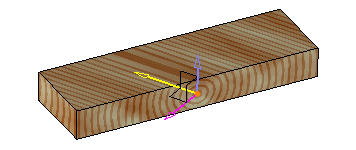
 

  • Manual:

  • Origin: origin of the largest linear edge.

  • First direction: the largest linear edge.

  • Second direction: linear edge adjacent to the first one.

  • If there is no linear edge, nothing is done. In this mode, the fiber operation will be placed just after the operation that created the first shape, in order to avoid invalidities if the edge or the origin were to disappear
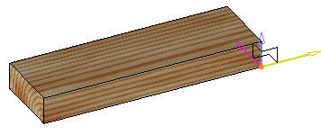


  • Automatic:

  •  Shape: the shape that was just created.


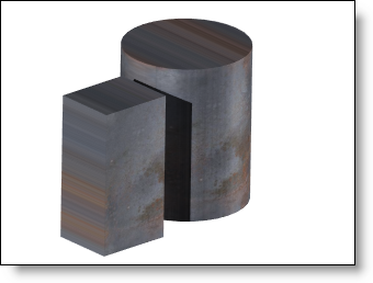
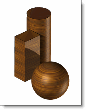
  • Managed by material:

  • Frame: frame giving the direction of the fibers. A frame is automatically created, based on the largest linear edge, its origin and the adjacent edge. It will orient the fibers if the material is anisotropic

  • Shape: the shape that was just created.


Available options:


The Create frame option allows to create the frame according to the fiber directions (origin and axes along the 3 given directions).

This frame is created in the Analysis stage by default, but it can be moved in the Design stage thanks to the Others > Change Stage... contextual command on the Fiber Management operation.


Additional Information:


By default, the material orientation is applied according to the absolute frame.

The 3 given directions correspond with the 3 axes X,Y and Z of the new frame that will be used.


Default fibers orientation according to the absolute frame.

Fibers orientation defined according to the part edges.
The frame is the one created by the option "Create frame".


This option allows you to modify the texture mapping locally to a part with application parameters, independently of the part definition.


  • Texture mapping : Choose a texture mapping.


  • Inherited: the mapping used is the one specified in the texture definition document.

  • Planar: the image is plated on the object regarding a planar projection to be able to minimize image deformations. Parameters of this category are the same than Auto-axis category.

  • Auto-axis: the image is plated on the object in the 3 orthogonal directions by minimized image deformations. The parameters of this category are the same than Planar category.


  • Cylindrical: the image is rolled around a cylindrical object to be able to minimize image deformations. The width of the image corresponds to the rolling, the height will be applied regarding the cylinder height.

  • Spherical: the image is rolled around a spherical object to be able to minimize image deformations. The width and the height correspond to the rolling on the sphere.


Parametric : this mode should be used when working with FBX files attached textures. TopSolid will then use the mapping defined in the FBX model which specifies the correspondence of each pf the texture points on the polyhedron.


Color sacle factor :

Before applying a color scale factor.

With color scale factor of 3 (Inherited mapping mode).


Color rotation angle :

Before applying a color rotation angle.

With 45° color rotation angle (Inherited mapping mode)


Normal scale factor:

Before applying a normal scale factor.


With a normal scale factor  of 0.5 (auto axis mapping mode value 800mm).


Normal rotation angle :

Before applying a normal rotation angle.

With a normal rotation angle of 75° (auto axis mapping mode value 100mm).


If the material does not have normals, then the settings for scale factor normals and rotation angle will have no effect.