|
- Manufacturer:
It allows you to choose the library among the available ones
in TopSolid.
- Type:
4 ejector types are available: Cylindrical,
Shouldered, Blade and Tubular.
- Use
the best code: If the Dimensioning
option describes bellow is checked, it is possible to
choose the best code, it means the more appropriated,
taking in account of this dimensioning.
- Code
: Choose the wanted code in the drop down menu.
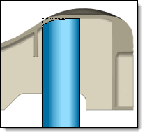
Two positioning modes are available:
 Point : This mode
allows you to insert an ejector on a point. This one can be
selected on the shape with shrink, on the core/cavity blocks
or on the plates... the pin center will be aligned with this
point. It is also possible to create the wanted point with
the "special inputs"
Point : This mode
allows you to insert an ejector on a point. This one can be
selected on the shape with shrink, on the core/cavity blocks
or on the plates... the pin center will be aligned with this
point. It is also possible to create the wanted point with
the "special inputs"  . .

|
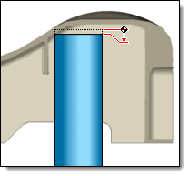
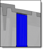
By
default, if an edge is selected to position a blade
pin, the blade orientation will be the chosen edge
one. The blade will be centered on this edges. Graphics
arrows allow you to align a blade side with the selected
edge. |
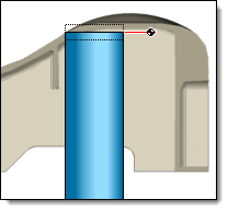
 Sketch: It is possible to select a sketch to
insert several pins in the same operation. It is also possible
to create a new sketch with the "special inputs"
.
Sketch: It is possible to select a sketch to
insert several pins in the same operation. It is also possible
to create a new sketch with the "special inputs"
.
|
With
the sketch mode, the pins need to be inserted in automatic
mode. Then, to get specific settings, you need to edit
the pin to modify. |
With the sketch
mode, deux positioning are available:
 Points : A pin will be inserted on
each point in the sketch. They will have all the same
diameter. Points : A pin will be inserted on
each point in the sketch. They will have all the same
diameter.- Identical
pins by repetition: allows to put an pin, and to
repeat it by a sketch pattern. The pattern is automatically
built from the point sketch chosen at the time of inclusion.

|
This option
is only available in Point
Sketch mode. It is necessary to uncheck the circle mode. All the pins will
be identical, no limitation check is performed
on repeated pins. |
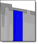
 Circles : It is possible to
position the pins by circles. They will have the same
diameter of the circles, or the first higher diameter
available in the code list. Circles : It is possible to
position the pins by circles. They will have the same
diameter of the circles, or the first higher diameter
available in the code list. Blade pin symbols :
It is possible
to position the blade pins by including a Flat
pin symbol family in the
sketch. These symbol families are available in the
TopSolid
Tooling, Symbols, Ejector Pins Symbols, Flat or Keyed
Flat.
Blade pin symbols :
It is possible
to position the blade pins by including a Flat
pin symbol family in the
sketch. These symbol families are available in the
TopSolid
Tooling, Symbols, Ejector Pins Symbols, Flat or Keyed
Flat.

|
Checking the
Profiles
option when the symbol is included allows you
to select the sketch graphically in the sketch
area. Preview
 : Including
many pins simultaneously in sketch mode in a large
mould file can be quite time-consuming. In order
to avoid the calculation of the preview of each
ejector, it is possible to activate or not this
preview.
: Including
many pins simultaneously in sketch mode in a large
mould file can be quite time-consuming. In order
to avoid the calculation of the preview of each
ejector, it is possible to activate or not this
preview. |
|

 icon or select the Mold > Pin...
command from the drop-down menu.
icon or select the Mold > Pin...
command from the drop-down menu. .
.