This command allows to imprint a property,a
text or a sketch on a part face.
Marking if often used to display Manufacturing
Index ant/or Mounting Index
properties.
Creation stages / Use:
Select Surface
> Marking... command from the drop-down menu.
Select the
marking type:
Select the
shape to modify.
Specify the
property, the text or the sketch to mark.
Position
the property or the text.
Validate.
|
Text to mark: select the property.
Temporary text: enter
the text to display (see Information area below for more details).
Family: select the font
to use.
Size: enter the font
size. |
|
Text to mark: enter the text
to mark on the shape.
Family: select the font
to use.
Size: enter the font
size. |
|
Planar sketch: select sketch
to mark. |

|
Marking with Automated
mode creates an auxiliary
element named Sketches to
Mark with all marking sketches inside. It is this auxiliary
entity that will be displayed in upper assemblies (with possibility
to show/hide it).
In the part document, marking is represented
by the temporary text until a marking operation is done in the
assembly containing the part. The auxiliary element Sketches
to Mark is then automatically hidded and the imprint is
done on the face of the part.
|
|
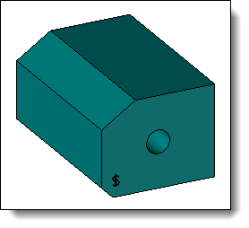
Marking
for mounting index with $
symbol as temporary text |
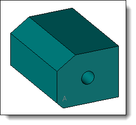
After
marking operation in the assembly containing the part,
the temporary text is replaced by the value of the property
and the imprint is done on the face of the part |
|

|
Marking operation created from the
assembly in which the part has been included will modify it according
to settings of parts
operation options. |
Available Options:
|
Frame:
text positioning frame.
Text orientation: text
angle according to the reference direction below.
Reference direction:
select the text reference direction. TopSolid
will use the X frame axis when this field is empty.
Alignment:

|
Left vertical line: it is the vertical line passing
by the left extremity of the text. |
|

|
Center vertical line:
it is the vertical line passing by
the center of the text.. |
|

|
Right vertical line: it is the vertical line passing
by the right extremity of the text. |

|

|
Lower horizontal line:
it is the lower horizontal line including
letter like "j". |

|

|
Base horizontal line:
it is the root horizontal line without
letter like "j". |
|

|
Center horizontal line:
it is the horizontal line passing
by the center of the text. |

|

|
Upper horizontal line:
it is the upper horizontal line of
the text. |

|
|
|
This
option will not imprint the sketch on the part but will store
all marking attributes to display sketch on upper documents.
This allows to not reduce performances since no edges are adding
to the shape.
In the operation tree, Ø
symbol is added in front of the lightweight marking. |
|
This option allows to assign a machining
process to the operation. This machining process is recognized
by TopSolid'Cam. It can also assign a color to the operation..
- Select a machining
process document in the drop-down list.
- Select a process in the
drop-down list.
|
Modifications / Additional
information:
With
Automated mode, user can enter
a part of the property to use. TopSolid
will filter the properties drop-down list to display properties containing
entered text.
It is possible to use several
properties in the same marking operation. Use &
symbol to seperate them. To add text between properties you must add
".
'Mounting Index'&'Manufacturing Index'
'Mounting Index'&" - "&'Manufacturing
Index'