Automatic Bar Nesting


This command allows to nest extruded bar in support bars of the same section type.

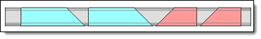
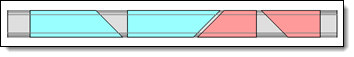
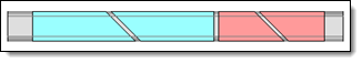
After defining the Extruded Bar Nesting Characteristics, for both extruded bars and support, the parts will be automatically placed in the bars to optimize the loss rate of the bars required to place all the parts.


Creation stages / Use:


Click the icon or select the Nesting > Automatic Bar Nesting... command from the drop-down menu.


  1. Activate the Parts tab. Drag the parts to nest from the project tree.

  2. Activate the Supports tab. Drag the supports to use from the project tree.

  3. Choose the strategy.

  4. Choose the options.

  5. Validate .


  • Only Extruded bar parts can be nested.

  • The parts are placed according to the Z axis of the reference frame defined by the Extruded Bar Nesting Characteristics command.

  • Only one type of section, identical between parts and support, can be nested at a time.


Save: This option allows to save settings. The nesting operation is created but it is not computed and assemblies documents are not created.

Compute: This option allows to launch the computing of the nesting that could be saved.


The nesting window is composed of seven tabs:


This tab allows to select the parts to nest by dragging them from the project tree and by filling the placing informations (quantity, rotation, cluster ...)

  • Parts are added by drag/drop:

    • of part or assembly documents into the parts list dialog.

A part can be placed if it follows these rules:

  • The document provides the Nesting Extruded Bar Component function. To do it, use the Extruded Bar Nesting Characteristics command.

    • or BOM. It allows you to:

    • Nest parts and/or local parts of an assembly.

    • Add n times all the parts of an assembly.

    • If the BOM contains manufacturing indexes, these are transferred to the parts in the documents produced by the nesting.

  • The quantity of each part to nest can be modified.

  • Priority: The nesting  takes supports with a priority of 1 (the smallest value) and places parts regarding their priorities. Then supports with priority 2 are completed with residual parts, always by considering their priorities. And so on....
    Parts and supports priorities are independently considered.
    If no priority is given to the pieces, they will be placed in priority from the longest to the shortest.

  • The color of the placed piece is assigned automatically. However, it is possible to assign a different color to each piece.

  • Cluster: This option applies a strong constraint. The grouped part must be the only one nested until the desired number of part is placed. Then the other parts will be nested.

Nesting without cluster

.

Nesting with cluster

.

  • Allow flip:This option allows the flip of a part in the support to optimize the loss rate (on the X and Y axis of the reference frame).

  • Degrees of freedom: This option allows to define the allowed rotations of the part, according to its tube section, around the Z axis.

    • Free: Free rotation of the nested part from 0° to 360° with a step of 1°.

    • Interval: Rotation with minimum, maximum angle and a rotation step.  
      When nesting, the part can be rotated according to the defined interval. If the minimum angle is 0°, the maximum is 360° and the step 90°, the part can be rotated at 0°, 90°, 180°, 270° or 360°.

Nesting without rotations and without flip-flop.

Nesting with rotations, without flip-flop.

Nesting with rotations and flip-flop.


This tab allows to define the list of supports to use to nest parts and the nesting characteristics (quantities, border gaps).

  • Supports are added by drag/drop of part documents from the project tree into the supports list dialog. Use the Extruded Bar Nesting Characteristics command and select the Support mode.

  • Possibility to specify border gaps with different values on the left and on the right.

  • Only supports of the same section can be added. The priority will be given to the shortest support. It is still possible to modify these priorities by defining them in the dedicated column.


This tab allows to manage the nesting strategy.

  • Packing: Allows to define if the nested parts are on the left, or the right of the support. The loss is on the opposite side.

On the left: The packing is realized on the left of the support, the loss area is on the right.

On the right: The packing is realized on the right of the support, the loss area is on the left.

  • Cut gap: Gap between each part on the support.

  • Max time: This option allows you to limit the computing time allocated to the nesting.


The check of the consistency between the material of the part and the support can be activated. If it doesn't match, the nesting can't be validated.

It is possible to allow supports and parts without material. In this case, there will be no error.

  • The check of the consistency between the thickness of the tube and the support can be activated.

  • The Check quantity respected option allows to ensure that the requested quantity is respected.

  • The Invalid if a problem is detected option makes the document invalid if one of the strategy criterion isn't coherent (wrong quantity, material, thickness, ....)


This tab allows to manage default values for border gaps between parts and supports, the gap between supports, the text style to use and the template to use. These defaults values and options allow to fill the new documents dragged in this nesting.

  • The different gaps for all new dragged supports in the supports list can be filled with a default value.

  • The gap between supports can be filled by default.

  • The nesting text style can be selected or created. It is the text displayed in the nesting indicating the number of identically filled supports.


This tab allows you to choose the type of document created by the nesting. In the case of an assembly for example, the nesting generates assembly type documents with one support per document and nested parts.

  • For each type of document, a template can be associated.

  • Automatic mode allows to automatically associate the type of document created by the nesting according to the type of part document to be nested. The list of possible choices is then grayed out and only allows the selection of a compatible template document.


This tab summarize the contain of each placing. It displays the number of included support ( a support can be included several times if the parts quantity allows it) and the loss rate.

This tab is only displayed if the nesting has been calculated.


Modifications / Additional information:


To use a symmetrical part a Mirror part must be created and it must be added to the parts to nest.

When creating the mirror document, the Extruded Bar Nesting Characteristics analysis operation is derived.