
|
Two
section types can be chosen to create the pocket:
User: You can choose a sketch,
or create one from the "special inputs"  . This sketch define
the pocket section. . This sketch define
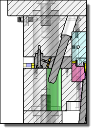
the pocket section. Model: This mode allows
you to choose a template contour to define the pocket. The
pocket parameters will be defined in the Drivers
section.
By default, we offer two models, Circular and Oblong. It is
possible to create your own templates, with providing on of
the available functions in the TopSolid
Tooling, Profiles, Angle Pin Pocket Process library. Code: It is possible to
choose a family code if the selected template is a component
with a family. This option is not available if there is no
family available.
Pocket depth is determined
as follows: Through:
if
this option is not checked, the depth is calculated according
to two different modes: Offset: The
depth will be given by the position of the pin, plus the
chosen
offset. This depth will be associative
to the position and the code of the finger. Depth: By selecting this mode, the
depth of the pocket is initialized to the exact height of
the pin. It is then possible to round this value and thus
create a "rounded" pocket height.

|
In Depth
mode, the depth value is not associative to the length
of the pin. |
|


 .
.


