The double click on a dimension component (dimension or projection line) allows to display handles coupled with reference geometries.
It is then possible to select a handle and slide it onto another geometry.
|
|
Available Options:
Dimension:
|
This cell allows the dimension style to use to be defined. |
Reference frame:
|
The frame defined in the main view is used as origin frame of measurements. In this mode, only the geometries resulting from the projection are supported.
|
Text:
|
|
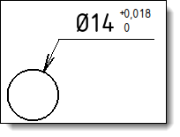
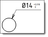
Tolerances:
|
This option allows you to add a tolerance to the dimension. Three types of tolerance are available:
|
Format:
|
Display the name and size of font used Use the Font cell to activate the button and then modify the settings (font, style, size, effects, etc.).
Displays the number of decimals of the length and angle dimensions. Use the unit format cell to turn on the button and modify the settings (number of decimals, display zeros).
For tolerances with overlaid texts (tolerance difference, symmetric tolerance difference, etc...), this option allows to assign a factor to the height defined in the tolerance font.
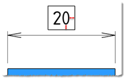
Allows to select a text framing: None, underlined, framed, in an obround, under an arc or between brackets. When the underline, framed, in an obround or under an arc mode is selected, you can define a margin between the text and the decoration.
Allows to set the color of the dimension.
Allows to set the layer of the dimension.
|
Advanced options:
|
Secondary dimension:
Geometry:
Extremities:
|
|
When an option is modified, its button remembers changes. |
Modifications:
With the command dialog close, the use of the right button on an existing dimension allows:
To Edit it to modify its settings (reference geometries, style and format).
To hide it.
To delete it.
To rename it.
To deport it.
To break it (available for the coordinate dimension).
To add comment (its position can then be changed using contextual commands for reorganize, stack and unstack annotations).
With the command dialog open, the use of the right button on an existing dimension allows to delete it.
 button.