This command allows to create datum targets for ISO geometric tolerancing
according to the ISO 5459 standard.
Creation stages / Use:
Select the Detailing > Datum target...
command from the drop-down menu.
Select the view on which you want to create datum
target.
Switch on the next step using the arrow.
Create Datum
target symbols.
Validate the datum targets sketch.
Select the datum target geometry.
Available options:
|
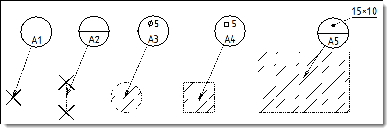
Allows
to set how to display the size of the selected geometry (point,
line or area). This size is displayed in the upper part of datum
target.
|
-
Square: square
symbol before the side value.
- Circle: diameter
symbol with diameter value.
- Rectangle:
length × width.
- Other: empty. |
Manual: enter
the text to be displayed. The Symbols
button at the end of the field allows to add special characters. Export type: allows to export or
not the text outside the datum target according to the Automatic, Exported
and None modes. The
Automatic mode will
export the text when it does not contain into the datum target.
|
Examples
of size display according to the selected geometry |
|
|
A verification of the uniqueness of the couple letter/number
is made on the 2D view.
|
|
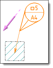
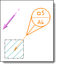
Allows
to add a movable target and define its properties.
|
|
Datum
target with movable target |
Datum
target with movable target and alignment
|
|
|
Allows
to define the framing of the note and its line color.
Font: Displays the name and size of the font
used. Use the Font cell to activate the button and then modify
the settings (font, height and style). The button displays
changes. Unit
format: allows to define units,
separator, precision, ... Target
frame size factor: allows to define
the size of the symbol. This size is the result of the factor
you entered multiplied by the height of the font. Movable
symbol size factor: allows to define
the size of the movable symbol. This size is the result of
the factor you entered multiplied by the height of the font. Export
dimension leader extremity marker type:
when the text of the size does not contain in the upper
part of the symbol it can be exported (automatically or manually).
This option allows to customize the type of end of the arrow. Color: To use another color, select the color cell and select a new one to use. Layer: Assign a layer to
the element. The layer can be created on the fly by clicking
the "+".
|
Modifications / Additional information:
Symbols and datum target can be created in a 3D document using annotations
commands and retrieve in a drafting document in two ways: