Constrained Linear Pattern
|
Constrained Linear Pattern |
This pattern allows you to distribute entities or operations between 2 points or on a plane with a centering mode and a distribution type.
Creation stages / Use:
Click the  icon or select the Construction >
Pattern > Constrained Linear Pattern... command from the drop-down
menu.
icon or select the Construction >
Pattern > Constrained Linear Pattern... command from the drop-down
menu.
Select the definition mode of the pattern:
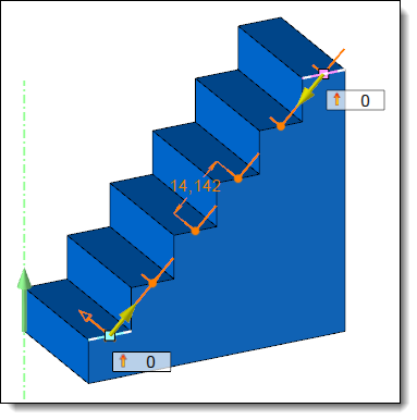
Between points: the pattern is created from a start point and an end point, a vertical direction which manage the orientation of the frame and an orientation.
|
|
Example of constrained linear pattern between 2 points with a Normal orientation (according to the 2 selected points). In this case, the vertical direction allows to define the frame orientation (the direction of the X axis is defined by the 2 points and the direction of the Y axis is defined by the vertical direction). |
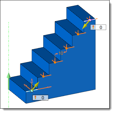
Example of constrained linear pattern between 2 points with the Vertical orientation. |
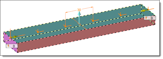
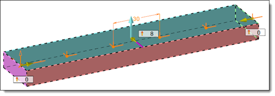
On plane: the pattern is created from a direction, a support plane, a start and an end geometry.
When the Automatic mode is checked, the faces or edges perpendicular to the selected direction are automatically selected as start and end geometries. When a face and an edge are matching this criteria, the priority is given to the face.
When the Automatic mode is unchecked, the direction is no longer asked, it is defined in the Axis position dialog.
Choose the distribution parameters:
Fixed count: the distribution is defined with a number of instance (Total count) and eventually, start and end margins.
Maximum distance: the distribution is defined with a maximum distance between instances and eventually a thickness which reduce the value of the maximum distance.
Step : the distribution is defined with a distance between instances.
See The Distribution Modes of the Constrained Linear Pattern page for more details.
Confirm the creation of the pattern with the  button.
|
This command produce a frame that can be used while creating a drilling or positioning a component. Thereby, the first instance of the drilling or the component will be positioned properly and may be repeated using this pattern. |
Available options:
Axis position:
|
When the On plane mode is selected, this dialog allows you to locate the axis with two ways:
These geometries should be straight (linear edges, axis or linear segment) or planar (faces, planes).
|
Distribution:
|
Edge to edge: This option allows you to position an occurrence on each extremities of the pattern. It is available with Distance maximum the mode only.
Margins: The margins allows you to reduce the total length (distance between the start and end points or length of the selected plane), they can be the same (equal margins) or different (distinct margins).
Center: This option allows you to center the pattern on the remaining length (total length minus margins). It is available with Step the mode only. When this option is unchecked and the margins are distinct, the value of the start margin will be strictly respected. |
Alternated numbering:
|
|
Result:
|
This area displays the values of the pattern (total distance, margins, step, number of occurrences). |
Advanced Options:
|
Create parameters: When this option is checked all the computed values are also available as parameters in the Entities tree. These parameters are stored in a sub-folder of the Parameters folder, the name of the pattern is used as suffix. |