Analyze Simulation: Thickness
|
|
Analyze Simulation: Thickness |
In a Strip document, this command makes it possible to analyze, using a color scale, the Thickness of a sheet metal part during its forming.
|
|
To get access to this command, the sheet metal part unfolding must have been calculated by using the global "unstamping" unfolding method through the en FTI (Forming Technologies Incorporated) calculation module. It is useful for the treatment of unbendable or undevelopable parts. See the Forming Flange Unfolding command for more details. |
|
|
|
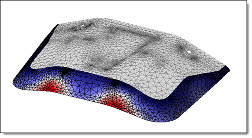
Simulation analysis of a local forming flange unfolding. |
Creation stages / Use:
Click on the icon  or select the Analyze > Analyze Simulation: Thickness... command from the drop-down menu.
Choose the result to view, if multiple unfolding have been created and proceed to the next step  .
.
Choose the color scale type
Validate  .
.
To quit the analyzis mode, simply click on the icon  above the color scale.
Available Options:
Analysis result to visualize:
|
|
|
Color Scale Type:
|
|
You can choose between two Scale type:
|
Colors Bar:
|
|
|
The color palette allows to modify the color scale in order to adapt it to the part geometry and so be able to visualize more easily the small variations.
The "-" or "+" under the color range allow to increase or reduce the curvature values range on the graduations.
By clicking on the small color square under the color palette, the color range can be either continuous or discrete.
You can reset the bar setting by using the contextual command "Reset color bar" available by right clicking on it. |
Modifications / Additional information:
By moving the mouse over the part meshing, it is possible to get the local value of the strain on this geometry.
It is possible to visualize the simulation result corresponding to the unfolding operation chosen from the tree of the entities by the command Analyze simulation. All these results are available in the Unfolding Simulation Results folder.
The Unfolding mesh and the Part additional mesh can be show or hide from the Unfolding Meshes folder, in the Entities tree.
Hide the Unfolding mesh automatically hides its associated Part additional mesh if it was computed with the Forming Flange Unfolding operation.