Forming Flange Unfolding
|
Forming Flange Unfolding |
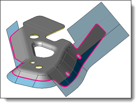
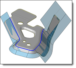
This command allows you to unfold a piece of part by an unfolding by unstamping simulation. The unfolding computation is realized from a mesh of one shape side, projected on a surface.
It automatizes the steps of part separation in two areas, creation of surface and mesh to unfold, unfold shape creation and finally union of this shape to the fixed side of the original shape.
Creation stages / Use:
Click the  icon or select Strip > Forming
Flange Unfolding... command from the drop-down menu.
icon or select Strip > Forming
Flange Unfolding... command from the drop-down menu.
Determine the side of the shape to be unfolded.
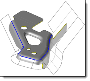
Create or select the projection surface.
Adjust the parameters of the mesh used for the unstamping simulation.
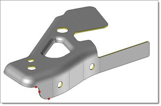
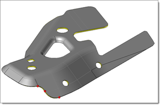
Validate  .
.
|
|
|
|
Available options:
Forming Flange Unfolding :
|
Two unfolding modes are available:
|
Mesh:
|
|
Advanced options:
|
|
Modifications / Additional information:
After editing the command in the operations tree, this is the forming unfolding building command which is edited. This command is included in the Forming Flange Unfolding operation.
Following commands are only proposed in contextual menu :
Show/Hide Trimming Sketch: This command allows you to Show/hide the trimming sketch used to create the unfolded shape.
Replace trimming sketch: The trimming sketch is produced by simulation. It is possible to sharpen/modify this result. Replace the sketch will produce a new 3D sketch, copied from the first one, and modifiable. Then, it will automatically replace the first sketch in the trimmed and thickened projection surface.
Restore computed trimming sketch: This command is only available when the computed sketch has been replaced. It is possible to go back to the first computed sketch. The other one that was created by copy is not deleted.


 Local
Local
 Global
 Normal
 Middle surface
 opposite
 Progressive
die
Progressive
die Draw die